Gardner Denver DELCOS 3100 Controller
Equipment Overview and Version Differentiation
DELCOS 3100 is a dedicated controller for Gardner Denver oil-free screw air compressors, available in three hardware versions:
FS version: Constant speed air compressor, star delta start
RS version: Variable frequency speed control air compressor, standard frequency converter
SR version: High end variable frequency drive, CAN communication, built-in more protection
Mandatory safety requirement: After the SR version is powered off, it must wait for 12 minutes until the capacitor has discharged before touching electrical components.
Operation panel and display
1. Button functions
Power on, stop, confirm, mute, menu, up, down, left, right, password key
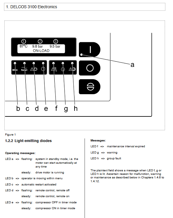
2. LED indicator light (key)
Meaning of LED status
A flashing standby, can automatically start
A normally lit motor is running
Flashing remote control shutdown
F Bright Maintenance Expires
G light alarm
H light fault shutdown
3. Display Area
First line: Final temperature R2, final pressure B2, pipe network pressure B1
Second line: Running status, faults, alarms, maintenance prompts
Supports 17 languages, press ← → to switch.
Menu structure (8 core menus)
MAINTENANCE SCHED. (Maintenance Plan)
Total running hours, loading hours
Countdown for air filter, water filter, and motor lubrication (0-9999h)
Overdue -100h automatic shutdown
Control Menu
Pressure upper and lower limits, target pressure
Automatic/continuous operation, remote, timed, automatic restart
Power off and restart time: 2-999s
RS485: Modbus/baud rate 4800/9600/19200
Fault Memory
Store the last 8 faults, with! Indicates a shutdown fault
Display fault code, description, and occurrence hours
RS/SR supports extended memory: time, status, speed, pressure
Limit Values
Design pressure, startup protection pressure difference, start stop temperature
Run delay of 90s, soft stop of 30s, star delta time of 8s
SR version includes maximum/minimum flow rate and external speed limit
Optional INPUTS (optional input)
3 programmable inputs: drainage, dryer, external faults, exhaust temperature, oil level, etc
Water (waterway)
The water change cycle is 24 hours, the maximum inflow time is 150 seconds, and the maximum drainage time is 150 seconds
Automatic water level regulation, high and low water level protection
TIMER Control
7 sets of power on/off timing+7 sets of pressure switching timing
Support execution by week/date/time
BASE LOAD SELECT. (Multi machine Joint Debugging BLS)
Master slave joint control, up to 1 master and 4 slaves
Pressure range, switching time, number of slaves, number of backup machines
RS/SR can configure the rated flow rate of each slave
Operation mode and control logic
Automatic operation: No delay shutdown required, automatic loading required under pressure
Continuous operation: The motor does not stop, always running without load/load
RS version frequency conversion mode: SPEED REGULATION ON/OFF/BYPASS bypass
SR version drive control: initialization, real-time monitoring of DC voltage and speed
Add/unload logic
FS: Pressure ≥ upper limit unloading, ≤ lower limit loading
RS/SR: Pressure follows target pressure, variable frequency regulation
Remote control function
Remote start stop: Passive contact, distance ≤ 20m
Remote pressure switching
FS version remote loading and unloading
Remote loading allowed (serial enabled)
Automatic restart: Short power outage * * ≤ 2s * * Automatic restart, can be set to unlimited restart
Waterway system control
Automatic water level regulation: high water level automatic drainage, low water level automatic replenishment
Timed water change: Change water according to the real clock cycle
Electromagnetic valve: Y8 water inlet, Y9 drainage, Y10 water cut-off
Fault: Supply, DRAINAGE, abnormal water level alarm/shutdown
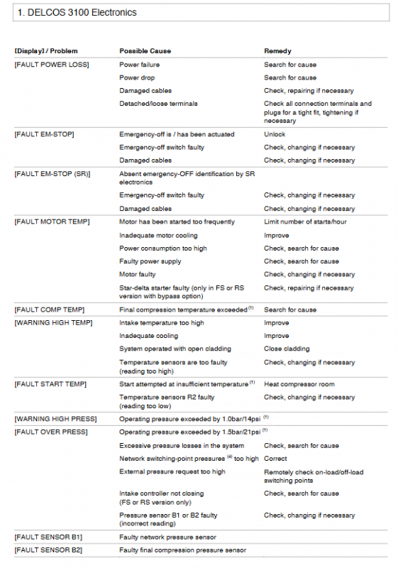
Fault and alarm system (core)
1. Shutdown fault (with!)
Power outage, emergency stop, motor overheating, exhaust overheating, low starting temperature
Overpressure, sensor malfunction, phase sequence error, frequency converter malfunction
There are a total of 54 driver faults in the SR version, including overcurrent, overvoltage, communication, and IGBT faults
2. Alarm (without stopping the machine)
High temperature warning, filter blockage, low oil level, low battery, external alarm
3. Fault handling principles
First eliminate the fault source → press the confirm button to reset → restart
Multi machine joint debugging BLS (Base Load Sequestration)
Applicable models: FS, RS, SR
Core competencies: Unified pressure range, automatic rotation, balanced operation hours
key parameters
Pressure bandwidth: ≥ 0.3bar
Switching time: 300s-999h
Number of slave machines: 0-4, backup machines: 0-4
Start delay: 5-30s
Pipeline inflation time: 0-60 minutes
Fault handling: The faulty machine is automatically queued to the end of the queue, and after repair, it is reinserted into the queue
Maintain standards
Can set air filter, water filter, and motor lubrication cycle: 0-9999h
Expired display MAINTENANCE ELAPSED
Overdue -100h: triggers FAULT MAINT PER shutdown protection
Reset the timer and eliminate the fault after maintenance is completed
Key questions and answers
Question 1: What are the core differences between the three versions of DELCOS 3100 (FS/RS/SR)? What air compressors are they used on?
answer:
FS version: Constant speed air compressor, star delta start, only loading and unloading control, no speed regulation function.
RS version: Variable frequency air compressor, supports speed regulation, and can switch between speed regulation/full speed/bypass mode.
SR version: High end integrated variable frequency drive, CAN communication, with 54 drive protections, speed limits, high-precision flow calculation, the most comprehensive safety and functionality.
Question 2: What is the function of multi machine joint debugging BLS? What are the three key parameters that must be considered when configuring?
answer:
BLS is a centralized control function for multiple air compressors, achieving unified pressure, automatic rotation, balanced wear and tear, and energy-saving operation.
Three key parameters that must be set:
Pressure range: upper and lower limit pressure difference ≥ 0.3bar, ensuring stable control
Switching time: Determine the rotation cycle to avoid long-term overloading of a single unit
Number of slave machines+number of backup machines: Define which machines participate in joint control and which only serve as backup machines
Question 3: What are the possible causes and steps for handling the FAULT SR-DRIVE (15) motor overcurrent fault in DELCOS 3100?
answer:
Reason:
Motor wiring error/cable damage
Motor insulation failure
Loose wiring of current sensor
Control board or driver board malfunction
Processing steps:
Check the three-phase wiring and insulation of the motor
Check the wiring and plug of the current sensor
Check the wiring between the drive and control board
Power off reset, if the fault persists, contact the manufacturer’s after-sales service