Siemens SINUMERIK 840C+SIMODRIVE 611-D Installation Guide
Basic Information
Product: SINUMERIK 840C/840CE (export version)+SIMODRIVE 611-D digital driver
Purpose: Installation and debugging of high-end CNC systems for lathes, milling machines, machining centers, and other high-end machine tools
Software version: Supports the entire series from V1. x to V6. x (with V3, V4, and V6 as the focus)
Structure: Installation Guide+Installation Checklist (Supporting Documents) in Two Parts
Core objective: Complete the first power on step by step → General cleaning → Loading machine data → Axis debugging → PLC debugging → Functional verification
Core Content Framework
1. Installation prerequisites and appearance inspection
Preconditions that must be met
Mechanical/electrical installation completed, axis movable, customer PLC pre debugged
Measurement system (encoder) wiring is correct, shielding and grounding comply with EMC specifications
Cable classification and wiring: separation of power and control lines, shielded single ended grounding
Grounding system: star grounding, equipotential connection, in accordance with DIN VDE 0160
check item
Emergency stop, grounding, encoder installation air gap, cable shielding, panel buttons and display
Module anti-static (MOS chips must not be touched without discharge)
Standard/export version differentiation: Export version CE does not have 5D interpolation and advanced IKA function
Installation checklist
Includes 9 major confirmations: prerequisites, appearance, software version, voltage testing, standard startup PLC、 Collar, functional testing, and data backup must be signed and archived.
2. General cleaning and standard activation
Core process (after SW3)
Set the CSB module startup switch to 1 (Startup)
Enter DIAGNOSIS → Select General Reset Mode
Execution:
FORCEDBOOT NCK-PLC
PLC GEN. RESET
FORMAT NCK AWS
DRIVE GEN. RESET (Digital Drive)
Configure memory (DRAM/SRAM): part programs UMS、IKA、 Axis data area allocation
Load standard machine tool data (STAND_T/STAND_M)
Exit the overall clearing, set CSB to 0, and restart the system
SW2 and previous simplified processes
Without MDD machine data dialog box, manually enter NC/PLC MD → initialize memory → clear PLC → end startup.
3. PLC installation and debugging
PLC CPU: 135 WB/WB2/WD, program loaded from hard disk after SW3
Programming device: Only supports PG7xx series, connected via RS232 or MMC
PG function via MMC (SW4+): PLC status, forcing, and variable monitoring can be directly performed on the panel
Debugging steps
PLC overall cleaning
Load user program ANW-PROG
Diagnosis: LED, ISTACK, timeout analysis, PLC status
Emergency stop, enable, safety logic verification
4. MMC Diagnosis and Services
MMC (Human Computer Communication) is responsible for system startup, hard disk management, and data backup
Service Function:
NC Service/Drive Service (Axis/Spindle Servo Monitoring)
Backup and Recovery (Streamer/PC Link)
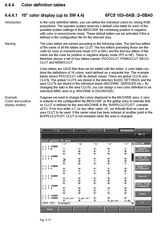
Configuration files: CONFIG, BED CONF (interface/color/menu)
Language switching, screen hard copy, UMS user data management
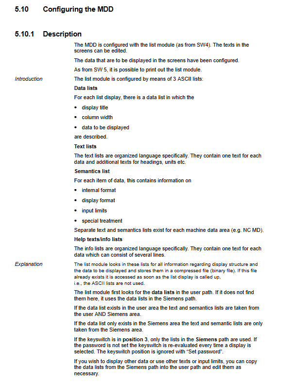
5. Machine tool data dialog box MDD
Unified configuration entrance
NC configuration and machine tool data
PLC configuration and machine tool data
Drive configuration (611D feed/spindle)
Loop data, IKA compensation data, user display
File function: Load/Save/Copy Machine Configuration Files
Common configurations
Add/replace driver module (single axis/dual axis, power mode switching)
Change of motor model, reloading of drive parameters
6. NC machine tool data and setting data
NC MD: Global, channel, axis, and spindle specific parameters
Resolution, acceleration, servo gain KV, position monitoring, contour monitoring
Zero return, soft limit, coordinate conversion, pitch compensation
MD bits: Function enablement (limit, compensation, spindle positioning, C-axis, etc.)
Set data SD: channel parameters, axis parameters, operational limitations
7. 611D Drive Machine Tool Data
MSD (spindle drive)+FDD (feed drive) parameters
Parameters of current loop, speed loop, and position loop
Servo Service Data (SSD): Monitoring and Optimization
Security Integration SI Parameters
8. PLC machine tool data (Chapter 8)
System data, functional block FB data, user data
Signal mapping, I/O configuration, safety logic parameters
9. Servo debugging tool
Measurement and optimization of current loop/velocity loop/position loop
Function generator signal testing
Quadrant error compensation QEC (regular/neural network version)
SERVO trace servo waveform capture (SW4+)
10. Shaft and spindle installation
Axis debugging
Resolution, pulse equivalence, sampling period
Direction confirmation, drift compensation, servo gain KV
Acceleration and deceleration, Jerk restriction, position monitoring, contour monitoring
Return to zero mode: Normal/Absolute Encoder/Distance Encoding Grid
Spindle debugging
Open loop, oscillation, positioning mode (M19), C-axis mode
Gear shifting, speed matching, spindle positioning, synchronization
Simulation spindle/digital spindle switching
11. Data backup and CPU replacement
Backup scope: NCK, PLC, driver, MD, SD, R parameters, tool parameters, PLC program
Backup media: Streamer tape, hard drive V24、 floppy disk
CPU replacement process: Power off → Replace → Restore data → Reset and restart → Verify
12. Advanced Function Description
Covering the core machine tool functions of 840C:
Pitch compensation, rotating shaft, continuous rotating shaft
Coordinate Conversion (Transmit/2D/3D)
Main shaft positioning, C-axis, electronic gear, synchronous main shaft, gantry shaft
Collision monitoring, ESR emergency stop rollback, UPS power-off protection
High speed data channel, master-slave torque control, temperature compensation
The most critical process: Standard startup 10 steps
Check wiring, grounding, shielding, emergency stop
Set the CSB start switch to 1 → power on
Enter DIAGNOSIS → General Reset
Clear NCK/Clear PLC/Clear Drive
Configure memory (DRAM RAM)
Load standard machine tool data
Input motor and drive parameters
Axis direction and drift compensation
Zero return and soft limit setting
Exit Total Clear → Set CSB to 0 → Restart → Function Test