OMRON C-series/CVM1/CV series analog I/O units
Core positioning
Applicable PLCs: C500/C1000H/C2000H, CVM1, CV500/CV1000/CV2000
Coverage Module: Analog Input (AD)+Analog Output (DA) Full Series
Core applications: Sensor signal acquisition, analog control, temperature/pressure/flow closed-loop
Communication method: IR/CIO area direct mapping+READ/WRIT dedicated instructions
Resolution: Mainstream 12 bit (1/4095), some economy models 10 bit (1/1023)
Module overview (9 series)
1) Analog input unit AD
3G2A5-AD001~005: 2 points, 12 bits, fixed range (1~5V/0~10V/± 10V, etc.)
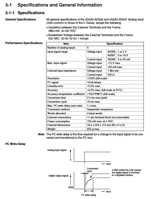
3G2A5-AD006~007: 4 points, 10 positions, low cost
C500-AD101: 8-point, 12 bit, independent range for each point, mean/peak/break detection
C500-AD501: 16 o’clock, 12 bit, differential input, scaling/filtering/alarm/EEPROM
2) Analog output unit DA
3G2A5-DA001~005: 2 points, 12 bits, fixed range
C500-DA101: 4-point, 12 bit, voltage/current optional
C500-DA103: 4-point, ± 10V bipolar
C500-DA501: 8-point, 12 bit, independent range for each point, ramp/limiter/EEPROM
Core Technical Parameters (General)
Resolution: Mainly 12 bits (4095), AD006/007 is 10 bits (1023)
Input range: 0~5V/0~10V/± 5V/± 10V/0~20mA/4~20mA
Output range: 0~10V/± 10V/0~20mA/4~20mA
Conversion time: 2.5~25ms/point
Isolation: Input – CPU photoelectric isolation; No isolation between channels
Power supply: 5VDC backplane, some models require external 24V
Installation: PLC backplane, cannot be installed on SYSMAC BUS slave station (except for some models)
Most important: working mode (2/4 word mode)
1) Two word mode (high-speed)
Batch read and write using READ/WRIT instructions
Fast speed, occupying less IR area
Only supports: CPU rack, expansion rack, SYSMAC BUS/2 slave station
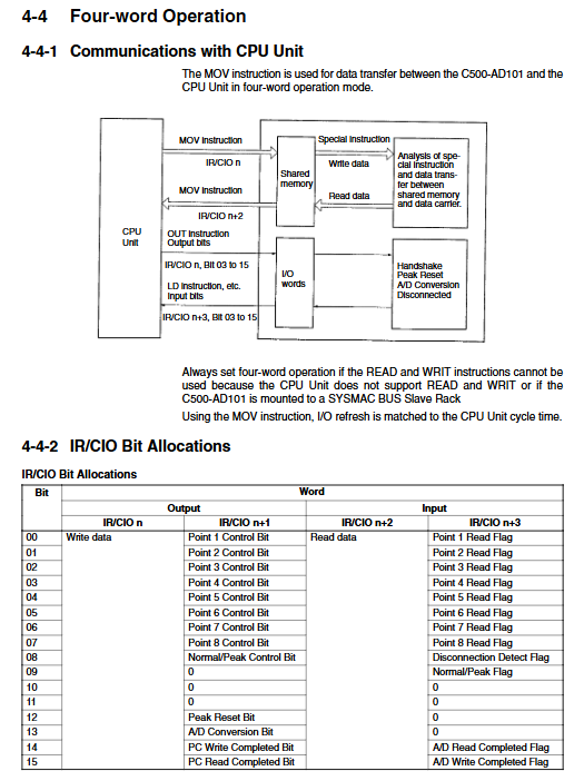
2) Four character mode (compatible)
Use MOV command to access point by point
The strongest compatibility
Support: All racks (including SYSMAC BUS slave)
Rule: AD101/DA101/DA501 must switch modes with a switch
Core functions (exclusive to advanced models)
AD101/AD501/DA501 support
Free range setting: independent voltage/current at each point
Scaling engineering quantity conversion: directly output engineering units
Mean filtering: Suppressing noise
Peak holding: Capture maximum value
Wire breakage detection: 4-20mA wire breakage alarm
Upper and lower limit alarm: Over range output flag
EEPROM storage parameters: power down save
Wiring and DIP settings (most commonly used)
1) General wiring rules
Voltage input:+connected to signal+, – connected to signal ground
Current input: V – and I must be short circuited-
Shielded wire: single ended grounded, away from power lines
Unused channel: positive and negative short circuits, anti-interference error message
2) DIP switch function
Set range: 0~10V/± 10V/4~20mA
Switch between two character/four character mode
Set power down output to hold/reset to zero
IR/CIO bit allocation (core)
Each module occupies 2/4 IR words
Bit0~11: AD conversion data/DA output data
Bit15: Bipolar symbol bit (1=negative)
Status bits: busy signal, completion flag, alarm, disconnection
Programming instructions (must be mastered)
Read (88): Read AD data/Write DA parameters
WRIT (87): Writing DA output/configuring AD
MOV: Simple Four Word Mode Transfer
BCD, BIN: Data format conversion
Example: AD value → BCD quantity → display/control
Typical application process
Power off → Set DIP range and mode
Wiring (voltage/current)
Power on → Confirm that the RUN light is on
Read AD raw values with READ
Perform filtering/calibration/engineering quantity conversion
Write DA output control valve/frequency converter using WRIT
Troubleshooting (most common)
No input: Range DIP set incorrectly, current not short circuited, wire disconnected
Reading drift: poor grounding, unused channels not short circuited
Output not moving: Two word/four word mode mismatch, instruction not executed
Alarm light on: Over range, external power supply missing, parameter error