M&C SP2006-H/DIL series heated dilution gas sampling probe
Basic Information
Product: SP ® Series Heating Dilution Sampling Probe
Model: SP2006-H/DIL (180 ℃), SP2006-H280/DIL (280 ℃)
Usage: Continuous sampling and online dilution of flue gas/process gas, used for toxic gas, humidity measurement, and emission monitoring
Version: V1.00.02
Compliance: CE (EMC 2014/30/EU, Low Voltage 2014/35/EU)
Application scenarios: Non explosion zones, smoke emissions, process gas analysis, dilution/anti condensation conditions required
Core functions and principles
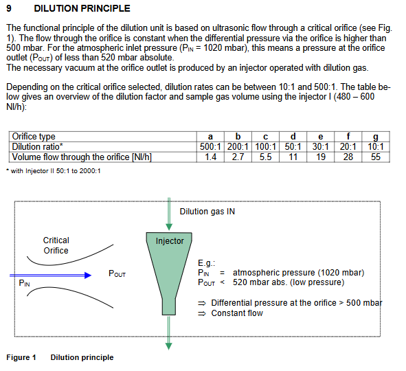
1. Working principle: Dilution principle of critical nozzle
Based on supersonic critical nozzle: When the pressure difference before and after the nozzle is greater than 0.5 bar (g), the flow rate remains constant
Vacuum is generated by an injector and driven by a diluent gas
Dilution ratio: 10:1~500:1 (Injector I); 50:1 ~ 2000:1(Injector II)
Advantages: Not affected by process temperature/atmospheric pressure/micro pressure fluctuations, stable measurement
2. Key features
Full process heating: probe+dilution unit integrated heating, anti condensation, anti acid corrosion
Preheat the dilution gas to the probe temperature to avoid sample cooling
Modular design, supporting bypass, blowback, isolation valve, calibration gas interface
Extremely low sampling flow, fast response, and low loss
Technical Parameters (Key Summary)
Heating temperature: 180 ℃/280 ℃
Dilution ratio: a (500:1), b (200:1), c (100:1), d (50:1), e (30:1, standard) f(20:1)、g(10:1)
Sample flow rate: 1.4… 55 Nl/h (with nozzle)
Dilution gas pressure: inlet min 4.5 bar (g), max 16 bar (g)
Material: 316Ti, quartz FKM(Viton)、 graphite
Weight: Approximately 30kg
Power supply: 230VAC/50Hz or 115V/60Hz, heating 800W
Pressure fluctuation impact: 50mbar fluctuation → error<1%
Model and Options (Modular Configuration)
SP2006-H/DIL: 180 ℃, without ball valve
SP2006-H280/DIL: 280 ℃, no ball valve
SP2006-H/DIL-VA: Manual ball valve with heating
SP2006-H/DIL-B: with bypass injector (exhaust)
SP2006-H/DIL-BR: with bypass injector (reflux process)
SP2006-H/DIL-I: with 1 voltage control+2 meters+installation package
SP2006-H/DIL-VA-MS1: equipped with 2 pressure controls and 3 meters (for bypass)
Optional: Backblowing (BB/BBF), 2L air storage tank, external ceramic filter
Safety Notice (Mandatory Compliance)
Not suitable for use in explosion-proof areas
Live working is only allowed for professional electrical personnel
Before starting up, it is necessary to confirm that the voltage is consistent with the nameplate
Cut off gas, power, and cooling before maintenance
Do not touch high temperature surfaces, protective gloves must be worn
When the low temperature alarm (heating failure) occurs, the dilution gas must be cut off
The sample gas may be corrosive and requires protection
Structure and Installation
1. Structural composition
Probe body+heating system
Filter (ceramic/fiberglass)
Dilution unit (critical nozzle+injector)
Bypass unit (optional)
Backblowing system (optional)
Temperature controller (70304G)+electrical junction box
19 “control disk-S/- S1 (optional)
2. Installation points
Installation position: Easy to maintain, tilted about 10 ° downwards to facilitate condensate reflux
Flange: Standard 3 “150lbs
To avoid radiant heat exceeding 60 ℃, it is necessary to install insulation panels
The filter needs to be checked for sealing regularly
3. Gas path connection (specification)
Dilution gas/calibration gas/vacuum gauge: 1/4“
Diluted sample gas outlet/blowback: 3/8“
Card sleeve connector+support sleeve must be used for sealing inspection
It is recommended to use a heat tracing pipeline for long pipelines
4. Electrical connection
Power supply: L/N/PE, cable ≥ 3 × 1.5mm ²
Temperature controller: 70304G, connected to PT100 or Fe CuNi thermocouple
The low temperature alarm contact must be connected to cut off the dilution gas
Recommended temperature resistant cable with external main switch and fuse
Initial Starting and Debugging
First, heat up: turn on the power and raise the temperature for about 2 hours to reach the set temperature
Re ventilation: It is strictly prohibited to introduce dilution gas before reaching the temperature
Adjust the pressure of the dilution gas to make the vacuum gauge>-0.6 bar
Check flow rate, vacuum, sealing, and heating stability
The bypass model needs to set the bypass pressure according to the curve
Calibration
Must be calibrated under operating conditions
Calibration gas pressure>0.7 bar
No bypass: Calibration air flow rate ≥ 3 times nozzle flow rate
There is a bypass: the calibrated air flow rate is greater than the total flow rate of the bypass and nozzle by 10%
Adjust the dilution ratio by fine-tuning the dilution gas pressure
Closing Down
Blow with inert gas before shutdown to prevent residual condensation of corrosive components
First cut off the gas, then cut off the power for cooling
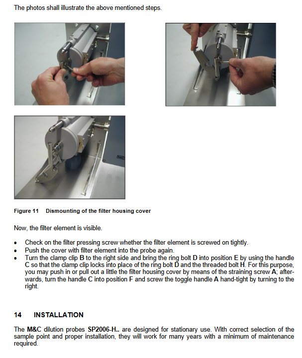
Maintenance and Repair (Core Chapter)
1. Daily maintenance: replace filter element and seal
Stop gas supply, cut off power for cooling
Open the quick opening filter cover
Replace the filter element and Viton seal ring
Tighten in cold state, then re tighten after hot state
No need to disassemble the entire machine for maintenance
2. Disassembly of dilution/bypass module
After cooling, open the casing
Loosen the rolling nut and clamp
Remove the module and prohibit mechanical needle cleaning of the nozzle
Only ultrasonic cleaning of nozzles and sprayers is possible
Check and replace O-ring (Viton)
3. Key taboos
Strictly prohibit mechanical dredging of critical nozzles
Protective goggles and anti-corrosion gloves must be worn for maintenance
Spare parts list (commonly used)
Filter element: Ceramic 2 µ m/Fiberglass 0.1 µ m
Sealing: Viton O-ring, flange gasket
Heating core PT100、 thermocouple
Injector, dilution module, bypass module
Filter cover assembly, clamp, compression screw