Allen Bradley Guardmaster 440R series safety relay
Product classification and hardware features
Six major product positioning
CI/SI (main control basic type): single group dual channel safety input, CI three mechanical safety contacts, SI two mechanical outputs, with built-in SWS single wire safety output, used for single safety device basic circuit;
DI/DIS (Dual Input Main Control): Two independent dual channel safety inputs (IN1/IN2), DI mechanical relay output, DIS is OSSD solid-state transistor output; Support SWS input+output, can be used as two safety devices and logic and/or control;
EM (Instant Expansion Module): No local safety input, only SWS signal input, four mechanical safety outputs, used to expand the number of safety contacts;
EMD (Delay Expansion Module): SWS input with delay output function, supporting three working modes: power-off delay, power on delay, and jog JOG, configured with timing parameters through B1/B2 terminals.
2 Hardware commonalities
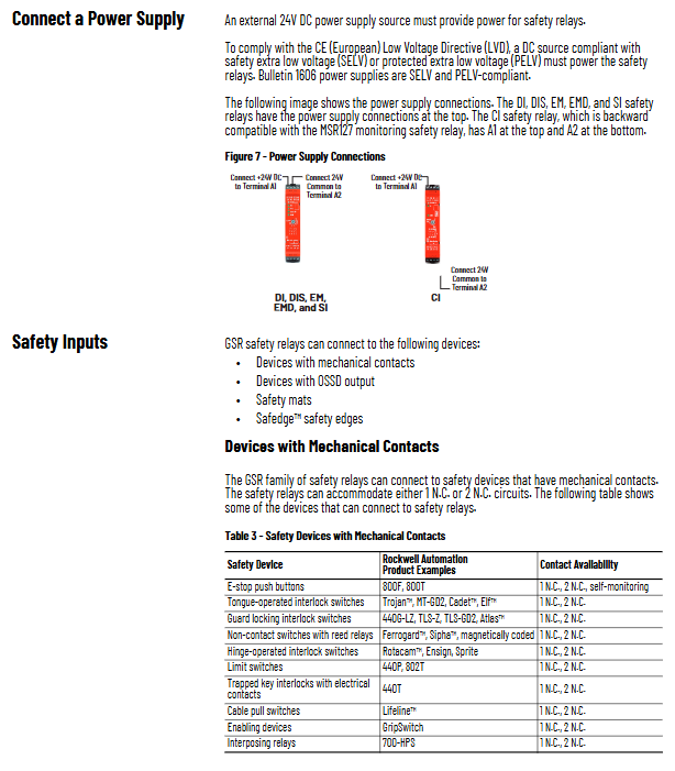
Installation: Standard 22.5mm width DIN rail buckle installation, plug-in terminal, terminal tightening torque 0.4N · m;
Unified power supply: DC24V (20.4~26.4V PELV/SELV safety power supply);
Panel indicator lights: PWR/Fault fault light, IN input indicator light, OUT output indicator light, EMD with B1/LOGIC IN status light;
Configuration method: Set logic, reset, and delay parameters for the multi bit dip switch on the panel, and save the configuration to EEPROM when powered off;
Communication: DI/DIS/SI/EM/EMD comes with an onboard fiber optic bus and is connected to EtherNet/IP with a 440R-ENETR Ethernet module. The upper level Studio5000 can view status and faults through AOP configuration.
3-core SWS single wire safety bus
The entire series comes standard with * * L11 (SWS output), L12 (SWS input) * * single wire safety interface:
Signal waveform: pulse with a cycle of 4ms (1ms+0.5ms pulse combination), measured with a multimeter at 8-9V;
Drive capability: A single L11 can connect up to 10 parallel L12 channels, while EM only transfers signals without any drive margin;
Wiring: Single segment cables can be up to 30m long, and shielded wires are recommended for long cables to achieve cascading expansion of safety circuits with multiple safety relays.
Input/output definition and wiring specifications
1. Safety input classification (S11/S21 are internal pulse test terminals, S12/S22/S32/442 are signal input terminals)
Mechanical normally closed devices (emergency stop, safety door, limit switch): S11 → one end of the switch, S12 → the other end of the switch, the relay periodically sends pulses to detect short circuits between lines and to ground;
OSSD solid-state output devices (safety grating, laser scanner): No need to connect S11/S21, directly connect the two OSSD wires to S12/S22, and the device comes with a built-in short-circuit self-test;
Safety carpet/safety edge: double wire short-circuit structure, DI/DIS requires AND logic to be set by dialing, and wiring capacitance will affect the pulse waveform.
Pulse parameters: CI pulse period of 14ms, DI/DIS/SI approximately 12.2ms, instrument no-load DC voltage CI ≈ 19V, DI/S11 ≈ 14V/S21 ≈ 18V.
2. Reset terminal S34 (standard for all series of main control models)
Two reset modes (dial selection)
Automatic reset: S34 is normally connected to 24V, and the safety circuit closes and automatically engages the output;
Manual reset of monitoring: It takes 250ms~3s for the high and low level to jump (button jog). After the safety circuit is closed, it must be manually reset, and full body intrusion protection is mandatory.
3 output differentiation
Mechanical Contact (CI/DI/SI/EM/EMD): Passive normally open safety contact, AC250V/DC24V load, EMD output with delay;
DIS OSSD solid-state output: 14/24 (1.5A, capacity ≤ 1.6 μ F), 34/44 (0.5A, resistant to 9 μ F large capacitor load), used for servo STO and inverter safety terminals;
Auxiliary outputs: CI (41/42), DI/DIS/SI (Y32), EM/EMD (X32), auxiliary conduction when safety output is disconnected, used for PLC fault feedback.
4 EMD specific B1/B2 terminals
B1 Suspension: Non triggered power-off delay;
B1 short B2: Can trigger power outage delay again;
B1 connected to 24V: JOG jog mode.
Configure the five step process
Power off, switch all dialing codes to 0 (configure the starting position);
Power on, the PWR red light flashes 1Hz and enters configuration mode;
Dial according to application settings (reset mode, input and SWS logic, EMD delay level);
Check the gear position based on the number of flashing indicator lights (flashing times=dialing value);
Power off and restart again, store parameters in EEPROM, complete configuration within 5 minutes, otherwise an error will be reported.
DI/DIS logic gear
1/5:(IN1 OR IN2) OR SWS; 2/6:(IN1 AND IN2) OR SWS; 3/7:(IN1 OR IN2) AND SWS; 4/8: (IN1 AND IN2) AND SWS.
EMD Delay Configuration
RANGE+TIME dual dial code, divided into short (0.1~1s) and long (10~3000s) levels, realizing custom power-off delay/power on delay/jog time.
Three major timing functions (EMD only)
Cannot trigger power outage delay again: SWS starts timing after disconnection, and does not reset when reconnected during timing;
Re triggered power-off delay (B1-B2 short circuit): During the timing process, SWS closes again, and the timer resets to zero and restarts;
JOG jog (B1 connected to 24V): SWS active+JOG terminal powered on, output timed conduction, forced disconnection after timed end, intermittent for 500ms before triggering again.
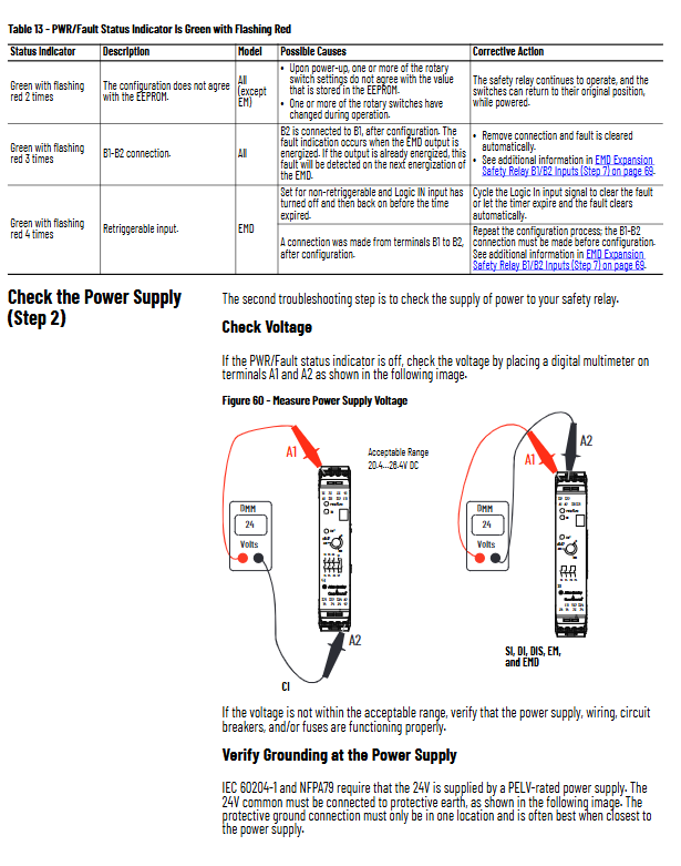
Panel indicator lights and fault codes (PWR light flashing times=fault type)
Solution to the cause of flashing frequency fault
Power off and restart after completing the configuration of 1Hz constant flashing configuration mode
Reconfigure if the two dialing codes do not match the stored parameters
3 carpet connections with OR logic changed to AND logic
4 times input line short circuit/carpet compression short circuit troubleshooting circuit, reset
5 SWS short circuit/lower level fault checks on L11/L12 wiring
6 times DIS output short circuit/large capacity capacitor misconnected 14/24, changed to 34/44
Green constant+red intermittent: can recover minor faults; Always red: Hardware damage needs to be replaced.
Standardization steps for troubleshooting
Check the PWR/Fault indicator light and locate the fault category;
Measure the power supply of A1/A2 at 20.4~26.4V, and check the power supply and grounding (PELV power supply 24V negative single point grounding);
Measure the pulse voltage of the IN terminal and distinguish between broken wires/short circuits/cable capacitance exceeding the standard;
Detect the waveform and voltage of SWS bus, and replace the shielding of long lines;
Measure the voltage level of the reset terminal of S34 and investigate the adhesion of the reset circuit contacts;
Measure the voltage on the load side of the safety output, distinguish between contact burnout and load short circuit;
EMD additionally detects B1/B2 wiring and gear settings.
Key influencing factors: excessive cable capacitance, high line resistance, input pulse interference, ignoring short pulses within 7ms, and 30ms input recovery time.
Communication and upper level functions
Multiple safety relays (up to 6) are combined with a 440R-ENETR Ethernet gateway to form an EtherNet/IP site;
Studio5000 imports AOP files and reads input status, output status, fault codes, and reset status online;
The gateway has a built-in webpage, and the browser can remotely view the status of the entire site’s security devices by entering the IP address.
Electrical parameters and environmental specifications
Working temperature: -5 ℃~+55 ℃, storage and transportation -20~+70 ℃;
Protection: IP20 body, NEMA1/IP40 cabinet installation;
Safety certification: SIL3, ISO13849-1 Cat.4/PLE, EN60204, CE/UKCA/UL;
PFH hazard failure rate is at level 10 ⁻⁹, and MTTFd meets the 20-year mission period.
Application wiring example
The manual includes six classic wiring diagrams, including emergency stop, safety door, safety carpet, grating, multi machine SWS cascade, EM delayed shutdown, and JOG jog, covering common industrial solutions such as single machine protection, multi zone interlocking, and frequency converter ST control.