IFM O3D series time-of-flight 3D industrial sensor usage instructions
Product Fundamentals and Hardware Specifications
Product models: O3D300/O3D302 (short focus), O3D310/O312 (long focus), integrated with built-in infrared LED lighting, lens focal length in different specifications, and industrial protection for the housing.
interface configuration
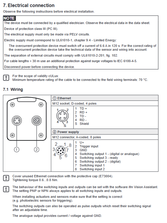
M12 8-core power supply/IO port: 24VDC power supply, 3-channel programmable digital input/output (IO1/IO2/IO3, PNP/NPN software switching), hardware trigger input;
M12 D-encoded Ethernet: 100Mbps network, supports TCP/IP, EtherNet/IP, PROFINET IO protocols, and only enables one type of bus at a time;
Installation and environment: DIN bracket/screw fixation, recommended installation height according to lens specifications, ambient temperature -20~+55 ℃, avoid direct sunlight (>8klx sunlight interference for distance measurement);
Supporting software: ifm Vision Assistant, free PC configuration, can create up to 32 independent detection programs (Applications), which can be switched and called.
Hardware installation and electrical wiring
Power supply: standard DC24V PELV power supply, reverse protection;
Trigger method: ① Hardware terminal trigger ② Bus instruction software trigger (t/T instruction) ③ Free continuous acquisition;
IO definition: DI can be triggered by external optoelectronics for incoming materials, DO can output OK/NG, shortage, full, and fault signals, and the output status can be read and written through the bus.
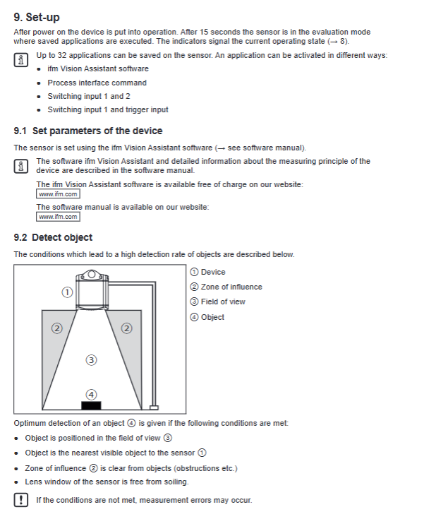
Built in five standard detection applications (sensor core functions)
The ROI area can be taught within the software, and 32 sets of programs can be freely switched. All results are uploaded to the PLC via Ethernet:
Integrity testing: Determine the shortage/excess/empty warehouse of materials in the area, and output qualified/over full/under material codes;
Level monitoring: detects the height of the material surface and triggers upper and lower limit alarms;
Dimension measurement: rectangular prism length, width, and height, center XYZ coordinates, deflection angle, and detection quality coefficient;
Robot Pick&Place: Multi object recognition, output quantity, geometric dimensions, six axis coordinates, rotation angle, adapted for robotic arm grasping;
Depalletising: Identification of stack layers, determination of layer height, presence of partitions, presence of abnormal debris, collision prevention, and differentiation of cardboard/bagged materials.
Each application result includes: status code, measurement value, and identification quality (0~100).
Panel indicator lights, device status
4 LEDs: power supply, network communication, operation, malfunction; When there is a malfunction, the PWR light flashes and the fault code can be read through the E command.
Software Configuration and Program Management
The upper level IFM Vision Assistant completes: field of view calibration, ROI drawing, parameter teaching, exposure time, frame rate setting, and output data format configuration;
The device can store up to 32 sets of application programs, which can be remotely switched through: ① Two way DI binary encoding static selection program ② Pulse counting selection (gate control+pulse) ③ Bus a instruction;
Parameter backup: Export the configuration file before firmware upgrade/sensor replacement, and import the new machine with one click.
Communication system (three major communication methods)
1. TCP/IP (ASCII protocol, default port 50010)
Process Interface (PCIC) custom output protocol V3 is the default, format:<ticket number>L length<content>CRLF;
Synchronous instruction (T – single photo feedback), asynchronous active upload (p instruction start stop);
Customizable output content: star+data+stop frame header and footer, supports floating-point to 16 bit integer conversion, scaling offset configuration;
Can upload: ROI measurement value, full frame image (5 types of images: distance/X/Y/confidence/grayscale), device temperature, frame rate, and computation time.
2 EtherNet/IP
Input assembly: PLC issues instruction words; Output assembly: Sensor feedback measurement, fault, statistical data;
The instruction adopts a bit triggered handshake, supporting synchronous triggering, program switching, reading and writing IO, and reading faults.
3 PROFINET IO
Fixed input/output message structure, single connection, GSDML configuration, communication logic follows EtherNet/IP handshake rules.
Serial/Network Control Universal Instruction Set (Process Command)
Complete ASCII instructions in the appendix of the manual:
Command function
A+Number switch specified application
A? Check the total number of stored programs and the current activation number
c/C? Write/Read PCIC Custom Output JSON Configuration
E? Read the current fault code
Temporary modification of application parameters (disassembly length and width, partition enable, etc.)
G? Read device IP/MAC/firmware and other information
H? Full Instruction Help List
I? Read raw image data
o/O? Set/Read IO Port Level
Asynchronous trigger T? Synchronous trigger
P start stop asynchronous data reporting
S? Statistics (total number of tests/qualified/defective)
v/V? Modify/query protocol version (V1~V4)
Image data format
TCP image packets are divided into multiple data chunks (Chunks), including:
Normalized amplitude plot, original amplitude, radial distance plot, XYZ Cartesian coordinate plot, confidence plot;
Single block includes: block type, size, image width and height, pixel format, timestamp;
The confidence map consists of 8 pixels, with each bit representing faults such as pixel saturation, invalidity, and insufficient signal-to-noise ratio.
Classification of fault codes
Hardware category: power supply overvoltage and undervoltage, lighting overheating, output short circuit; Configuration class: illegal program, incorrect parameters; Acquisition class: triggering overflow, image abnormality, E? Command can read 8-bit decimal fault codes.
Maintenance and firmware upgrade
Cleaning: Wipe the lens with a dust-free cloth and glass cleaner, and do not scratch the lens;
Firmware: Vision Assistant online upgrade, be sure to export parameter backups before upgrading;
Spare parts replacement: New sensors can be put into production by importing backup parameters.