BECKHOFF CX1000 Series Modular Embedded Industrial PC Hardware Manual
Beifu CX1000 series modular embedded industrial PC hardware manual, aimed at automation professionals, provides a complete introduction to product architecture, hardware specifications, interface definition, installation and wiring, fault diagnosis, disassembly and scrapping, and accessory services.
Product Overview
2.1 Product positioning and applicable scenarios
CX1000 is a rail type modular control system designed for automation scenarios with industrial PC computing power requirements but limited budget. It is modularly assembled and installed in control cabinets/junction boxes.
Support screenless (headless) operation: Communication control is achieved through network and serial ports, without the need for a monitor or keyboard;
Support local visualization: Equipped with DVI interface for external Beifu control panel or universal display, touch signal is connected through USB;
The core relies on PC104 (16 bit ISA) bus to achieve interconnection between modules, and components can be freely selected as needed.
2.2 Overall System Architecture
The entire system consists of four categories: CPU main module, power module, system interface module, and fieldbus module. It can be expanded with external devices such as UPS, bus terminals, and fieldbus boxes
Core combination: CPU module+CX1100 series power module as the basic unit;
Expansion interfaces: system interface modules such as serial port, audio, DVI/USB, etc;
Bus Expansion: Supports master/slave modules such as Profibus, CANopen, DeviceNet, SERCOS, Lightbus, etc;
Software system: Equipped with TwinCAT automation software, it realizes IEC 61131-3 standard PLC and multi axis motion control (process functions such as flying saw, electronic gear, cam, etc.).
2.3 Operation and Programming Methods
Operating System: Optional Windows CE.net, Windows XP Embedded;
Programming method: WinCE system is programmed remotely through Ethernet; XP embedded systems can be integrated with OPC servers to connect with SCADA, achieving control and visualization integration;
Task capability: Supports up to 4 user tasks and can synchronously run servo axis control tasks.
Detailed explanation of core hardware modules
3.1 CPU Basic Module (CX1000-0000)
3.1.1 Basic Parameters
Processor: Compatible with Pentium MMX, with a main frequency of 266MHz;
Storage/Memory: Two configurations -16MB Flash+32MB RAM, 64MB Flash+128MB RAM (XP Embedded systems must use this high-end configuration);
Standard interfaces: RJ45 Ethernet, 9-pin RS232 serial port;
Expansion slot: 1 Type II Compact Flash (CF card) slot for additional storage;
Auxiliary configuration: battery powered real-time clock, standard passive cooling module CX1000-COOL;
Size and weight: 57 × 100 × 91mm, basic model about 355g, with DVI/USB version about 435g;
Power supply: It is uniformly powered by the backend power module through the PC104 bus.
3.1.2 Indicator lights (LED)
There are a total of 5 diagnostic lights: PWR (power supply), Link (network connection), 100MBit (100Mbps network), Activity (network data interaction), HDD (CF card read-write).
3.1.3 Model subdivision rules
Divided into multiple models based on memory, system, interface, and TwinCAT software:
Memory: 16MB Flash+32MB RAM/64MB Flash+128MB RAM;
Interface: Basic version (Ethernet+RS232), expansion version (with additional DVI+dual USB);
System: Windows CE.net, Windows XP Embedded (requires a minimum CF card size of 128MB);
Software: No TwinCAT, TwinCAT PLC runtime, TwinCAT PLC+NC motion control runtime.
3.1.4 Key interfaces and CF card specifications
Ethernet RJ45: defines 8-pin signal transmission and reception, cross line direct connection to equipment, and through line connection to switches;
RS232 (COM1): Standard 9-pin D-Sub interface, fully defining signals such as data transmission and reception, handshake, and grounding;
CF card slot: only used as a storage interface, hot plugging (power-off operation) is strictly prohibited; We only recommend using Beifu industrial grade CF cards (wide temperature range, high erase life, maximum temperature resistance of 85 ℃), equipped with a dedicated pop-up structure.
3.1.5 PC104 bus
Using 104 ISA standard signals, CX1000 adds 8 expansion signals (I ² C, USB, power control, etc.) on this basis, which is the core bus for interconnection and intercommunication of all modules. The document fully labels all pin definitions.
3.2 System Interface Module (CX1000-N Series)
The module size is uniformly 19 × 100 × 91mm, weighing about 80g. It is factory fixed on the CPU module and cannot be modified on site. It is powered by PC104 bus and comes in 4 models:
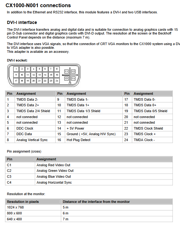
CX1000-N001: 1 channel DVI-I+2 channels USB 1.1
DVI-Iis compatible with digital/analog VGA signals and can be converted to traditional CRT displays; The longest transmission distance is 7m, and the resolution decreases with distance; Complete annotation of 29 pin DVI pin definitions;
USB is a standard A-type port, defined as 4-pin, used for external touch screens or peripherals.
CX1000-N002: Two RS232 channels (COM2/COM3), maximum baud rate of 115kbit/s, simplified 9-pin interface definition.
CX1000-N003: Audio interface (line in, microphone in, line out/headphone), 3.5mm audio dock, built-in buzzer, maximum output power of 200mW.
CX1000-N005: Two way optoelectronic isolation RS422/RS485, maximum baud rate 115kbit/s; Onboard 8-bit dip switch, configurable for echo, transmit/receive mode, and terminal resistance, cannot be used simultaneously with N002.
3.3 Power module (CX1100 series)
The input of the entire system is 24V DC (allowable fluctuation -15%~+20%), with a maximum power consumption of 30W. It is recommended to equip the front-end with a 2A fuse; Integrated 8KB NOVRAM (power-off secure storage process data), two lines of 16 character backlit LCD display screen, which can read and write display content through ADS protocol. Divided into 3 models:
CX1100-0001: Pure power supply module, no I/O interface, 5-pin pluggable terminal power supply, only 1 PWR power indicator light.
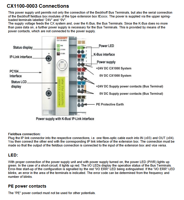
CX1100-0002: Integrated K-Bus interface, capable of connecting to Beckhoff bus terminals; Equipped with I/O RUN and I/O ERR diagnostic lights, and built-in 2KB I/O dual port memory.
CX1100-0003: Supports both K-Bus and IP Link fiber interfaces, and can expand fieldbus box modules; Built in 4KB I/O dual port memory, with terminals and indicator lights defined in the same way as 0002.
Indicator light rule: When the power is normal, the PWR light is green, and when there is a short circuit, it is red; If the I/O ERR light is constantly off, it indicates that the bus configuration is normal. If it flashes, a fault is reported, and the fault code can be interpreted by the frequency of flashing.
3.4 Fieldbus module
Supports Lightbus, Profibus DP, CANopen, DeviceNet (master/slave), SERCOS (master only), module size 38 × 100 × 91mm; the master module can be paired with Beifu’s complete set of bus components to build large-scale distributed systems, and the slave module can be used as a sub control system network.
Transportation, installation, and wiring
4.1 Transportation and unboxing
The equipment is resistant to vibration but not to severe impact. It is recommended to use the original packaging for transportation;
The environment with large temperature difference is prone to condensation, and the equipment needs to be left at room temperature before being powered on. The condensation state needs to wait for more than 12 hours;
Open the box and check the accessories, inspect the appearance for damage, and promptly contact after-sales if there are any abnormalities.
4.2 Mechanical installation requirements
Installation form: standard DIN rail installation, all modules have a uniform height of 100mm, compatible with 120mm standard junction box;
Size summary: The width of each module is different, and the total width of the whole machine is the sum of the widths of all splicing modules;
Ventilation regulations: The maximum ambient temperature is 55 ℃, and a 30mm ventilation gap must be reserved above and below the equipment; Installation posture that only allows vertical convection and prohibits blocking the heat dissipation holes;
Module assembly: The modules are directly assembled through the PC104 interface, and the white buckle at the bottom is used to fix the guide rail; The fieldbus module needs to be disassembled from the CPU side cover before splicing.
4.3 Wiring specifications
All modules are centrally powered by the power module through the PC104 bus, without the need for separate wiring;
Distinguish between 24V, 0V, grounding, UPS positive and negative terminals for power supply terminals, and strictly prohibit mixing other potentials for PE protection;
K-Bus and IP Link fibers need to be wired according to the input/output direction.
Fault diagnosis and troubleshooting
5.1 Interpretation of indicator light faults
Focusing on the CX1100-0002/0003 power module, the fault is determined by the flashing frequency of the I/O ERR light, including dozens of fault codes such as EEPROM verification errors, buffer overflow, bus terminal damage, communication abnormalities, etc., and corresponding troubleshooting and repair plans are provided.
5.2 Common faults and solutions
Possible causes and solutions for the fault phenomenon
The whole machine has no response, power supply interruption, damaged fuses. Check the fuses, measure the input voltage, and verify the wiring. If there are still abnormalities, contact after-sales service
Unable to complete boot boot. CF card damaged, system configuration error. Check CF card, verify system parameters, and contact after-sales service
System startup but abnormal control function, software or external device failure, docking software/device manufacturer troubleshooting
CF card read/write error. If the memory card or slot is damaged, replace it with a spare CF card for testing. If the fault persists, report for repair
Intermittent operation of equipment, internal hardware damage. Contact Beifu technical support
5.3 Hardware watchdog instructions
The hardware watchdog function is only supported by Beifu in the combination of Windows NT system and TwinCAT; Other systems require users to develop and adapt them themselves, and relevant hardware information can be downloaded from the official website.
Shutdown, disassembly, and scrapping
Disassembly steps
The entire machine must be powered off and stopped before performing disassembly operations;
Module disassembly: Pull down the white buckle at the bottom and remove the entire module from the guide rail;
Module separation: Use a flathead screwdriver to open the rear separation mechanism and slowly separate the PC104 interface. Do not forcefully plug or unplug.
Scrap disposal
After disassembling the equipment, electronic components are strictly recycled and disposed of in accordance with local electronic waste regulations; Unauthorized disassembly of the casing is prohibited as it may cause permanent damage to the equipment.