Basler DECS-250 Digital Excitation Control System Manual
Product General Information
1. Product model and communication type
Two mainstream models:
LN2SA1C: equipped with ControlNet communication;
LN2SA1D: equipped with Ethernet/IP DLR (Device Ring Network) communication;
The device can be paired with Rockwell RSLogix 5000 software to complete parameter programming and control.
2. Classification of core functions
(1) Excitation regulation mode (four main modes)
AVR automatic voltage regulation: mainstream mode, stable generator terminal voltage;
FCR excitation current manual adjustment: manually control the excitation current;
PF power factor regulation: constant unit power factor;
VAR reactive power regulation: Constant reactive power output of the unit.
(2) Auxiliary control function
Soft start: The voltage ramp builds up smoothly, and the initial voltage and rise time can be set;
Excitation limit: OEL over excitation limit, UEL under excitation limit, to protect the generator from operating in a safe range;
Low frequency compensation (V/Hz): prevents overheating of the iron core under low frequency conditions;
Line voltage drop compensation: compensates for the voltage loss of long-distance transmission lines;
Automatic mode tracking: No disturbance transition during multi-mode switching;
Redundant automatic switching: seamless switching when the primary and backup devices fail.
(3) Grid connection and load distribution
Supporting parallel operation of generators, providing three compensation methods: reactive power adjustment, cross current (differential) compensation, and active load balancing; Simultaneously supporting the synchronous grid connection function of single/double circuit breakers.
(4) Complete protection function (following power standards, labeled with ANSI protection code)
Full fault protection for generator and excitation system: demagnetization (40), reverse reactive power (40Q), phase sequence error (47), overcurrent (51), overvoltage (59), undervoltage (27), excitation overvoltage (59F), voltage transformer disconnection (60FL), frequency abnormality (81O/81U), reverse power (32R), excitation diode fault, permanent magnet generator (PMG) power loss, etc.
(5) Measurement function
Real time acquisition and display: a complete set of electrical parameters including three-phase voltage/current, active/reactive/apparent power, power factor, frequency, excitation voltage/current, electrical energy (kWh/kvarh/kVAh), synchronization parameters, diode ripple, load deviation, etc.
3. Hardware input/output
input
Voltage sampling: single-phase/three-phase generator voltage, single/double bus voltage (connected to VT transformer);
Current sampling: three-phase generator current, cross current (CT transformer, compatible with 1A/5A specifications);
Analog quantity: ± 10V remote set point;
DC control power supply, PMG excitation power supply, remote excitation enable.
output
Main excitation output: PWM power output, continuous 15A DC;
Relay contacts: Fault relays, redundant relays, cross current relays (all normally open contacts);
Load sharing interface: used for active power sharing among multiple units.
communication interface
Redundant RS-232 (DB9): primary and backup device linkage tracking;
ControlNet/Ethernet/IP: interface with PLC;
USB、 Network port: Factory testing only, not available to users.
Installation specifications
1. Receipt and Storage
Check the part number and appearance upon arrival, and immediately contact the logistics if there is any damage; Temporary storage should be placed in a dry and dust-free original packaging.
2. Installation environment and mechanical requirements
Environmental level: Pollution level 2, overvoltage category II;
Requirements for hazardous locations: Equipment must be installed in cabinets with an IP54 rating or higher, and cannot be installed outdoors naked; ATEX/IECEx Zone 2、 The North American Class I Div 2 scenario must strictly follow the explosion-proof wiring rules;
Installation posture: It must be installed vertically, otherwise the heat dissipation will fail and the equipment will age prematurely;
Space gap: left and right ≥ 63.5mm, up and down ≥ 101.6mm;
Transformation adaptation: Provide adapter board (part number 9440311102), which can directly replace old CGCM/BECGCM modules.
3. General requirements for wiring
Wire: Unified use of copper core wire, temperature resistance ≥ 105 ℃, voltage resistance ≥ 600V;
Grounding: The grounding terminal (56) of the chassis must use * * ≥ 3.3mm ² (12AWG) * * copper wire for single point grounding, and multiple devices must have independent grounding bars;
Shielded wire: Shielded twisted pair cables are preferred for voltage, current, communication, and excitation circuits, and the shielding layer is grounded according to terminal specifications;
CT safety rules: Open circuit is strictly prohibited on the secondary side of current transformers, and short-circuit terminals must be installed.
4. Terminal definition and wiring
(1) Left terminal block (core functional terminal)
Divide load sharing, excitation enable, shield grounding, generator/bus voltage sampling, current sampling, cross current circuit, control power supply, PMG power supply, excitation power output, chassis grounding, etc., and clarify the range of wire diameters suitable for each terminal.
(2) Right side interface
RS-232 (DB9): Redundant communication, using crossover lines, defining pins such as transmit/receive and ground;
ControlNet: Dual BNC interface (redundant networking);
Ethernet/IP DLR: dual RJ45 ring network interface;
USB/Ethernet port: factory specific, factory disabled.
5. Various circuit wiring schemes
Control power supply: DC 18~32V (nominal 24V), connected to BAT+/- terminal;
PMG working power supply: supports single-phase/three-phase, can be output from permanent magnet machine or generator (requires voltage transformer VT);
Excitation output: EXC+/- is the PWM power output, and redundant systems require parallel freewheeling diodes in the excitation winding;
Voltage sampling: supports multiple VT connections including single-phase, delta, three wire/four wire star, and dual bus;
Current sampling: three-phase CT connection, PSS function must be configured with three-phase current;
Cross current compensation: Multiple units are connected in parallel with a dedicated CT circuit for reactive power sharing, which can adjust the impedance of the circuit through an external resistor;
Remote analog input: ± 10V signal is used for remote constant value adjustment;
Remote excitation enable: 24V DC switch quantity control excitation switching.
6. Electrical parameters in hazardous areas
Clearly define the maximum voltage, current, power, and cable capacitance/inductance limits for the intrinsic safety circuit. The default parameters for the cable are 60pF/ft and 0.2 μ H/ft, which need to be matched with the parameters of the associated equipment.
Operating principle and operation
1. Hardware architecture
Integrated microprocessor ADC/DAC、 Various acquisition circuits, excitation power units, relays, and multiple communication modules use flash memory to store parameters.
2. Detailed explanation of the four major excitation regulation modes
Each mode is equipped with PID regulation algorithm, which can independently configure proportional, integral, derivative, and total gain; Simultaneously supporting internal set point tracking and mode switching rate adjustment.
3. Parallel operation compensation function
Reactive power regulation: When the load increases, the voltage drops proportionally, suitable for grid connected units;
Cross current compensation: Multiple units are connected in parallel to achieve equal distribution of reactive power, and the circuit gain is adjusted to adapt to different working conditions;
Line voltage drop compensation: compensates for the voltage loss of long-distance lines.
4. Limiting function (core protection)
(1) V/Hz low frequency limit
Double turning point, double slope adjustable curve, automatic voltage drop when frequency decreases, to prevent overheating of the generator core.
(2) OEL overexcitation limit
There are two modes: offline (single machine) and online (grid connected), each with high/medium/low current thresholds and delays, and a counter to prevent repeated overexcitation and burning of the excitation winding.
(3) UEL under excitation limit
Segmented line characteristics prevent generator phase loss and overheating of the end iron core. The curve can be customized according to multiple points of active power.
5. Comprehensive protection logic
All faults are divided into two categories: alarm and trip: excitation overvoltage, reverse reactive power, and PLC fault will directly cut off excitation; All fault states are uploaded to the PLC through communication tags, and fault relays can customize triggering conditions. Additional feature protection: Excitation diode monitoring, determining diode open/short circuit by detecting current ripple frequency.
6. Synchronous grid connection function
Supports three modes: automatic synchronization, allowed synchronization, and synchronization verification; Adapt to single/double busbars, different phase sequences/wiring groups, and can set voltage, frequency, phase locking windows and closing delays, while supporting empty busbar closing logic.
7. Load sharing
Active power sharing: Through the interaction of 0-5V analog signals, multiple units can evenly share the active load, and the adjustment rate and deviation limit can be set;
Reactive power sharing: Utilizing cross current circuits to achieve reactive power distribution in parallel units.
8. Redundant system
The main and backup DECS-250 devices track parameters in real-time through RS-232. In the event of a main device failure/disconnection, the backup device will take over without disturbance; Equipped with redundant relays to switch excitation output.
9. Measurement function
High precision collection of various electrical quantities and cumulative values of electrical energy, with overflow rules for electrical energy data and support for zeroing operations.
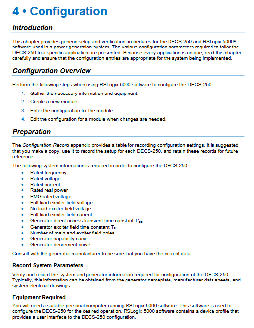
Parameter configuration
1. Configuration prerequisites
RSLogix 5000+RSNetWorx software is required to collect basic data such as generator nameplate, VT/CT ratio, excitation parameters, and motor characteristic curves in advance.
2. Module creation and key setting
Add 1407-CGCM module to the ControlLogix controller, supporting three electronic key modes: fully matched/compatible/disabled, to prevent module mismatches.
3. Configuration page (multi tab pagination)
All parameters are paginated by function, and each type of parameter has a range limit. After modification, some parameters need to be restarted/disabled for excitation to take effect:
Generator parameters: rated voltage, current, power, excitation parameters;
Transformer parameters: VT/CT wiring method, transformation ratio;
Excitation settings: soft start, excitation overvoltage, loss of current threshold;
V/Hz, OEL, UEL curve parameters;
PID gain: proportional/integral/derivative parameters of each regulating circuit;
Tracking and switching rate: mode tracking, redundant tracking, set point change rate;
Synchronization parameters: voltage/frequency/phase locking, bus offset compensation;
Protection settings: thresholds and delays for overcurrent, overvoltage, undervoltage, frequency, reverse power, etc;
Fault relays: Customize which faults trigger relay outputs.
4. Data classification
Configuration table: Basic parameters of the equipment, which can only be written when the excitation is turned off;
Non periodic table writing: parameters such as gain and compensation can also be modified during excitation operation.
Startup and Debugging
1. Safety preparation
Power off and hang up before homework, and take anti-static measures; The CT secondary side must be short circuited.
2. Essential tools
Programming computer, communication network card, dual channel recorder, voltage/current simulation source.
3. Step by step debugging process
Appearance and wiring inspection;
Power on, verify the control power supply and network communication status;
Static testing: Simulate voltage/current signals, verify sampling and protection functions;
Redundancy function test: manually switch between primary and backup machines to verify the switching logic;
Real machine debugging: Start the unit, test FCR and AVR modes in sequence, and set PID parameters;
Synchronous grid connection test: Verify the closing logic in the test position and normal position;
Full functional verification of parallel load, various limiters, and diode protection;
Finally archive all configuration parameters.
Software interface
1. Five communication data tables (based on ControlNet CIP protocol)
Periodic reading (input table): real-time status, all fault indicators, synchronization information, measurement values (time critical data);
Periodic writing (output table): mode selection, constant value, excitation enable, fault reset, synchronization command;
Non periodic reading: full measurement data, auxiliary parameters (non real time);
Non periodic writing: gain, voltage compensation, energy reset;
Configuration table: Fixed parameters at the bottom layer of the device.
2. Communication rules
Due to different firmware versions, there may be differences in the length of the data table, and it is necessary to match the message length;
The configuration table can only be written when the excitation is turned off, and non periodic writing is not limited by the excitation state;
Define a large number of tags corresponding to each state, parameter, and fault, which can be directly called in the PLC program.
3. Data format and range
Clearly define the data types, units, and value ranges of all analog and switch quantities, as well as the calculation and overflow rules for accumulated electrical energy.
Troubleshooting
Classify fault phenomena, causes, diagnostic methods, and solutions according to functional modules, covering the entire scenario:
Abnormal regulation of FCR/AVR/PF/VAR;
Adjustment, cross current, and line compensation faults;
Abnormal operation of OEL/UEL limiter;
Active load sharing failure;
Synchronization and grid connection failure;
Inaccurate measurement data;
ControlNet network malfunction (interpretation of indicator light status);
Redundant switching failure;
Various types of protection misoperation/refusal.
Network indicator lights: distinguish the on/off/flashing/red/green status of A/B channels and module status lights, corresponding to fault types (address duplication, link failure, module fatal error, etc.).
Technical specifications
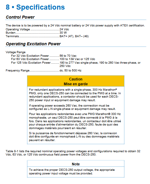
1. Power parameters
Control power supply: DC 18~32V (nominal 24V);
Working power supply (PMG/parallel input): distinguish the AC input range corresponding to the three excitation outputs of 32V/63V/125V;
2. Sampling circuit
Voltage sampling: 100~600Vac, each phase load < 1VA;
Current sampling: 1A/5A CT compatible, maximum 30A, load<1VA.
3. Excitation output
Continuous output of 15ADC; 10 second strong excitation 30Adc; Distinguish the minimum excitation resistance corresponding to different output voltages.
4. Accuracy indicators
AVR: steady-state accuracy ± 0.1%, full load ± 0.25%;
FCR、 Accuracy of reactive power and power factor circuits;
Dynamic indicators such as temperature drift and response time.
5. Protection and functional parameters
Organize all action thresholds, delays, and adjustment ranges for protection; Soft start V/Hz、 The parameter range for various compensations.
6. Environment and Machinery
Test standards for working temperature, humidity, vibration resistance, impact, salt spray, dielectric strength, etc.
7. Certification and Compliance
Explosion proof certification: UL, CSA, IECEx, ATEX (Class I Div 2/Zone 2);
Environmental protection: EU RoHS, China RoHS, with a total environmental protection service life of 40 years, in compliance with the WEEE directive;
Safety regulations: CE, cULus, etc.
Overcurrent characteristic curve
Built in 17 national/American standard inverse time and timed overcurrent curves, benchmarking the characteristics of traditional electromechanical relays such as ABB and GE;
Provide formulas for trip and reset calculations, as well as a table of curve constants;
Provide a conversion table between the electromechanical relay and the time scale of this equipment;
Supports voltage lockout overcurrent function, and can adjust the action setting according to the voltage ratio.