Beckhoff CX8110 Embedded Industrial PC
Product Overview and Hardware Architecture
1. Product positioning
The CX8110 belongs to the CX8100 series fanless embedded PC, equipped with the Windows Embedded Compact 7 system and running with TwinCAT 3 software. Specializing in distributed control and EtherCAT slave applications, it can be used as a lower level slave controller to interface with the main station, and can also independently complete PLC logic, motion control, and data acquisition; Supports K-bus and E-bus (EtherCAT) two types of Beckhoff buses, compatible with various bus terminals, widely used in small and medium-sized automation production lines, modular equipment, and remote IO sites.
2. Core hardware configuration
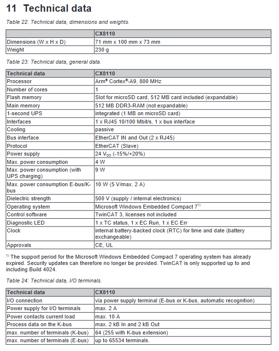
Processor: Single core Arm Cortex-A9, with a main frequency of 800MHz;
Memory: 512MB DDR3 (non expandable);
Storage: Standard 512MB SLC industrial grade microSD card, optional 16GB expansion card as system, program, and data storage medium;
Power supply: standard 24VDC (allowable -15%~+20% voltage fluctuation), normal power consumption of 4W, maximum 9W under UPS charging state, maximum 10W under full load of bus;
Built in function: Integrated 1-second supercapacitor UPS, can save up to 1MB of persistent data for a short period of time after power failure; The onboard CR2032 battery powered hardware real-time clock (RTC) maintains system time during power outages.
3. Interfaces and onboard components
Network port: 1-channel X001 (10/100Mbps Ethernet, used for programming, remote access, TCP/IP communication); 2-channel EtherCAT RJ45 interface (IN/OUT, standard slave interface, supporting 100Mbps).
Bus terminals: Automatically recognize K-bus and E-bus. K-bus supports up to 64 terminals (up to 255 after expansion), while E-bus theoretically supports 65534 terminals; The maximum power supply for the terminal is 2A, and the maximum load for the power contact is 10A.
Dialing switch (S101): A total of 8 valid dialing positions, used to set the device’s explicit device ID, supports hardware addressing and device replacement, and the remaining positions are reserved.
Function button: Reset button, long press to switch the device into configuration mode.
Status indicator lights: divided into TwinCAT status lights, EtherCAT operation/fault lights, and bus power lights, providing intuitive feedback on device operation, communication, and power supply status.
4. Nameplate information
The nameplate indicates the equipment model, hardware version, serial number, production date, X001 network port MAC address, power supply parameters, CE/UL certification; The device hostname is generated by default from the last three digits of the MAC address.
Installation, wiring and power on specifications
1. Installation of guide rails
The device is compatible with TS35/7.5 and TS35/15 standard DIN rails and adopts a snap on installation:
Installation posture: Priority should be given to horizontal installation, ensuring that the ventilation space above and below is ≥ 30mm. At this time, the working temperature range is -25 ℃~+60 ℃; Vertical installation only supports up to 50 ℃ ambient temperature.
Heat dissipation requirements: The equipment should be passively cooled, and the ventilation openings should not be obstructed. The control cabinet should have a reasonable layout of heat sources.
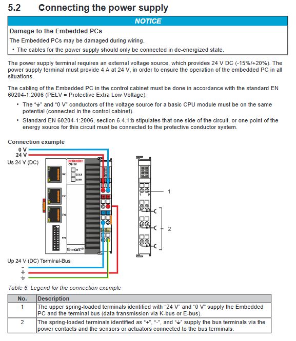
2. Power wiring
Terminal type: Spring type terminal block, suitable for 0.5-2.5mm ² cables, with a stripping length of 8-9mm.
Power supply differentiation: divided into main control module power supply (Us 24V) and bus terminal power supply (Up 24V). When the two power supplies are normal, the corresponding indicator light will turn green.
Wiring rules: Power off operation, strictly follow EN 60204-1 standard, PE protection ground and power supply 0V equipotential; When power is off, prioritize disconnecting the 24V positive pole and do not remove the 0V line separately.
UL requirement: NEC Class 2 isolated 24V power supply must be used, matched with a maximum 4A fuse, and the same type of power supply cannot be connected in series or parallel.
3. Communication cable specifications
Ethernet/EtherCAT both use Category 5 twisted pair cables, with a maximum length of 100m for a single cable; supporting various topologies such as star, wire, and ring.
System and Basic Configuration
1. Operating system
Pre installed Windows Embedded Compact 7, which has stopped Microsoft security updates, TwinCAT only supports up to the specified version. The system defaults to disabling CERHOST remote display and TELNET services. To enable them, you need to delete the corresponding registry file and restart the device. The system has built-in FTP service, and the firewall is enabled by default. It is recommended to use active FTP mode (open ports 20 and 21).
2. System image upgrade
Upgrading requires using a microSD card reader, completely clearing the storage card, and writing the new version image file; Before operation, it is necessary to back up the program and data to avoid file loss.
3. IP and Remote Configuration
The X001 network port defaults to DHCP for automatic IP acquisition, and static IP can also be manually set.
Beckhoff Device Manager: accessed through a browser, with the new version using HTTPS (port 443) and the old version using HTTP (port 80); Default account: Administrator, password: 1, supports hardware status viewing, parameter configuration, remote display switch.
Remote Desktop: After enabling the Remote Display function, the device system can be remotely controlled through the CERHOST tool.
4. Dial ID configuration
The S101 dialing code adopts binary encoding from 1 to 8 bits, and can customize the unique ID of the device. This configuration can be enabled by either hardware dialing or TwinCAT software, making it convenient for on-site devices to be quickly replaced and addressed.
TwinCAT Engineering Development and Configuration
1. Engineering connection and equipment scanning
The upper computer and CX8110 are connected to the same network, and in TwinCAT 3, the target device is searched through IP/hostname to establish ADS routing.
After the device is connected, it can automatically scan the K-bus/E-bus bus terminals and identify external devices such as IO modules and couplers.
2. Process data and variable configuration
Arm architecture devices have data alignment requirements: WORD/INT type requires 2-byte alignment, DWORD/DINT/REAL type requires 4-byte alignment; The data parsing differences between x86 and Arm architectures can be avoided by filling in variables. The EtherCAT slave device supports a maximum of 480 bytes of input and output data (256 PDO variables) each.
3. PLC engineering development
Supports the standard IEC 61131-3 programming language, capable of creating programs, associating hardware IO variables, and completing the entire process of compilation, activation, and execution.
4. Distributed Clock (DC) Configuration
The device supports EtherCAT distributed clock synchronization function and can be used as a slave station to interface with the higher-level master station
After enabling the synchronization function, the master-slave clock deviation (DcTimeDiff) can be monitored, with an ideal state deviation of<10ns and a qualified standard of<100ns.
The recommended synchronization task cycle is ≤ 5ms, and the CPU load should be controlled within 60%; Only in conjunction with EtherCAT (E-bus) distributed clock function, this function has no practical significance in K-bus mode.
Core function: 1-second UPS power-off protection
1. Functional principle
The onboard supercapacitor forms a 1-second UPS, which provides short-term power to the main control chip in the event of a power outage. The persistent data marked as VAR PERSISTENT is written to the microSD card, with a maximum reliable storage capacity of 1MB. This power supply does not supply power to the K-bus/E-bus bus bus bus, and data immediately becomes invalid after the bus is powered off.
2. Configuration and invocation
Call FB_S_UPS_CX81xx function block in PLC, and support four working modes: save data and quickly shut down, save data only, directly shut down, and only detect power status.
Persistent data generates Port_85x.bootdata files and backup files by default, which can be set through the system registry to automatically clean up invalid backups.
Power outage detection and UPS status can be read in real-time through the output pins of the function block, and data validity verification can be completed in conjunction with the system information structure.
3. Supporting functions
Built in F_CX81xx_DDRESS function, capable of reading hardware dialing status; The hardware real-time clock (RTC) can be read and written through dedicated function blocks, while providing registry options to fix system clock slow drift issues.
Communication protocol system
Ethernet/TCP/IP/UDP: Used for device programming, remote access, ADS communication, Modbus TCP, etc., it is the foundation of upper level interaction.
ADS protocol: TwinCAT core transmission protocol, based on TCP/UDP, used for data exchange between controllers, upper computers, and visualization systems. It defines addressing rules such as AMS NetID, ports, indexes, etc. The default TCP port is 48898.
EtherCAT: Real time industrial Ethernet, as the main bus of the device, supports various topologies and ensures high-speed periodic data exchange.
Compatible protocol stack: Supports interfaces such as OPC, ADS-OCX, ADSDLL, etc., and can be integrated with third-party software and upper level systems.
Fault diagnosis and status indication
1. Definition of indicator lights
TwinCAT lights: green=running, red=stop, blue=configuration mode.
EtherCAT (EC) light: Always on=link normal, flashing=data transmission, off=link failure.
Bus power light: The constant green light of Us/UP indicates that the corresponding power supply is normal.
2. K-bus fault diagnosis
Relying on the flashing frequency of the K-BUS ERR red indicator light to determine the fault code and fault location, covering more than ten types of faults such as bus disconnection, terminal damage, initialization errors, data anomalies, etc., and corresponding clear troubleshooting plans; Bus fault information can also be read through the internal status bits of TwinCAT.
3. E-bus (EtherCAT) diagnosis
By using the L/A indicator light to determine the status of the link and data, combined with parameters such as the slave status, distributed clock deviation, and frame errors within TwinCAT, the fault location is completed.
Maintenance, upkeep, and spare parts
1. Regular replacement cycle
Motherboard/RTC battery, UPS capacitor: It is recommended to replace them every 5 years;
Fan (this device does not have a fan), mechanical hard drive: 5 years;
MicroSD/flash storage media: It is recommended to replace them every 10 years.
2. Daily maintenance
Cleaning: After the power is turned off, use a soft damp cloth to wipe the machine body. Do not use corrosive agents or compressed air to prevent air vents from being blocked.
Battery replacement: Open the front cover to replace the CR2032 battery, strictly distinguish the positive and negative poles, and check the system time after replacement.
Storage medium: Only use Beifu original industrial grade microSD cards to avoid system failures caused by incompatible media.
3. Scrap disposal
The whole machine is classified and recycled as electronic waste, and the lithium battery is separately insulated and handed over to a professional organization for disposal.
Technical parameters and certification
Environmental parameters: working temperature -25 ℃~+60 ℃, storage -40 ℃~+85 ℃, humidity 5%~95% RH (no condensation); Vibration, impact, and EMC comply with the EN series industrial standards.
Interface speed: Ethernet 10/100Mbps, EtherCAT 100Mbps.
Certification: Passed international certifications such as CE, UL, FCC, etc., it belongs to Class A industrial digital equipment.
Optional accessories: 512MB, 16GB industrial grade microSD memory card.