Beckhoff AX2000 series digital servo amplifier
Product Overview
1. Product positioning and specifications
AX2000 is a modular digital servo amplifier that focuses on small and medium power servo drives. It is compatible with synchronous motors, linear motors, and some third-party motors, and supports three loop control of torque, speed, and position. It has functions such as electronic gears, master-slave tracking, and pulse direction control.
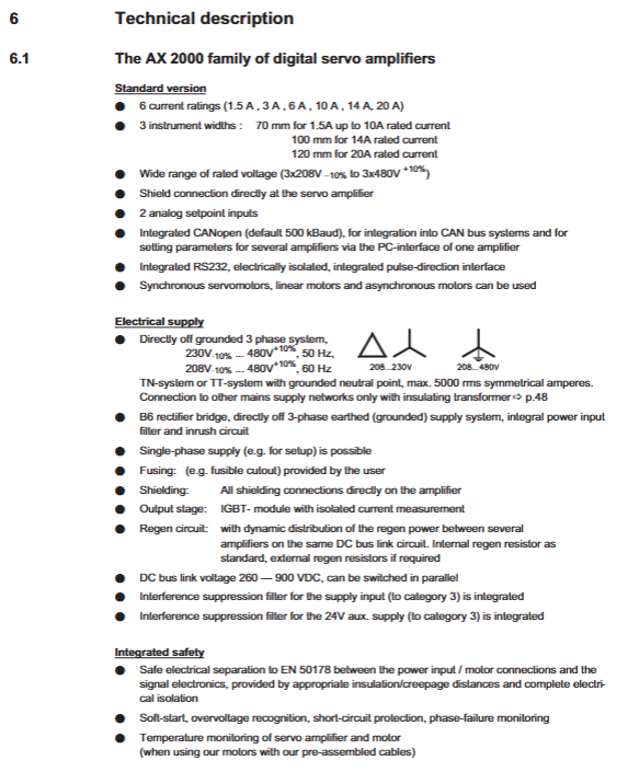
Current gear: 1.5A/3A/6A/10A/14A/20A multi specification models;
Power supply: three-phase 208-480V AC, single-phase 230V AC, compatible with 50/60Hz power grid;
Control power supply: 24VDC (-0%~+15%).
2. Structure and appearance
Cabinet rail installation design, protection level IP20;
Equipped with two buttons and three digital display screens on the front for parameter viewing, local settings, and fault code display;
The body integrates multiple sets of standard interfaces, supports expansion card slots, and has a compact overall structure.
3. Core hardware features
Power unit: using IGBT modules, with built-in rectification, inverter, and braking circuits; Equipped with built-in braking resistor as standard, supporting external braking resistor expansion;
Control circuit: current loop 62.5 μ s, speed loop 65/250 μ s, position loop 250 μ s, excellent dynamic response;
Encoder compatibility: fully supports Resolvers, rotary transformers SinCos、EnDat、Hiperface、BiSS、 Mainstream feedback types such as incremental encoders and SSI;
Interface capability: Standard configuration includes analog input, digital IO, RS232, CANopen; Multiple fieldbus expansion cards are available for selection.
4. Rules for nameplates and models
Label the model, serial number, electrical parameters, certification, and production date on the nameplate; The model code distinguishes current specifications, hardware versions, and optional functions.
Technical parameters
1. Environmental and mechanical parameters
Working temperature: 0~45 ℃, power reduction is required for overheating; Storage and transportation temperature: -25~70 ℃;
Humidity: 5%~95% RH, no condensation; Pollution level 2;
Altitude: No capacity reduction within 1000m, power reduction of 1.5% per 100m between 1000-2500m;
Anti vibration and noise meet industrial standards, with operating noise ≤ 45dB (A).
2. Electrical parameters
Main circuit: Three phase 208-480V AC, supporting single-phase power supply; The maximum DC bus voltage is 848V;
24V control power supply: external isolated power supply, built-in 3.15A fuse;
Braking circuit: distinguish between internal/external braking resistors, clarify the resistance value, continuous power, and peak power;
Cable specifications: According to the current matching wire diameter, distinguish the wire diameter, capacitance, and shielding requirements of power lines, feedback lines, and control lines.
3. Interface electrical specifications
Analog input: ± 10V differential, resolution 1.25mV, used for speed/torque setting;
Analog output: ± 10V, used for speed and current monitoring;
Digital IO: Optoelectronic isolation, compatible with PLC standard voltage levels;
Communication interface: RS232, CANopen (default 500kbit/s).
Transportation, storage, and unboxing
Transportation: Original packaging must be used to avoid strong impact and severe temperature changes; Ensure proper anti-static measures throughout the entire process;
Storage: Storage temperature -25~55 ℃, stacking has layer limitations; Storage for more than 1 year, the DC bus capacitor needs to be activated before power on (single-phase 230V no-load operation for 30 minutes);
Condensation treatment: When condensation occurs due to temperature difference, let it stand until completely dry before powering on;
Open box inspection: Check the goods, accessories, and documents, inspect for appearance damage, and contact the manufacturer for any abnormalities.
Mechanical installation
Installation location: limited to enclosed control cabinets, using DIN rail for vertical installation;
Heat dissipation requirements: Reserve ventilation space above and below, prohibit blocking air ducts, and rely on built-in fans for heat dissipation;
Surrounding requirements: Keep away from strong magnetic field equipment, and the installation plate should be made of conductive galvanized sheet to ensure overall equipotential;
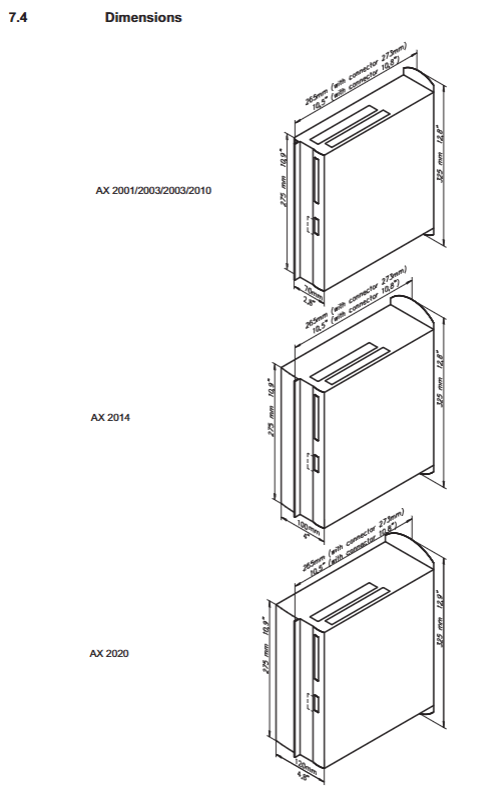
Installation dimensions: Provide drawings of the overall appearance, openings, and spacing of the entire series of models, specifying installation tolerances.
Electrical installation (emphasis)
1. General wiring rules
Separation of strong and weak electricity, with a distance of ≥ 200mm between the power line and the control line;
All cables must be shielded, and the shielding layer must be single ended/properly grounded;
Prohibit live wiring. Cut off the main power supply and lock it with a tag before wiring.
2. Detailed explanation of interface wiring
The overall machine interface is divided by function, including complete pin definitions and wiring diagrams:
Main power interface (X0): three-phase/single-phase mains input, distinguishing different grid connections;
24V control power supply (X4): isolated power supply, strictly prohibited from sharing ground with the main circuit;
DC bus (X7): supports multiple drivers in parallel to share the bus, and the bus cable has length and specification limitations;
Braking resistor interface (X8): default short-circuit uses built-in resistor, external braking resistor can only be connected after removing the short-circuit;
Motor interface (X9): Integrated motor power line, brake, temperature detection, cable length>25m must be equipped with motor reactor;
Feedback interface: Decomposer, dedicated interfaces for various encoders, specifying cable length and terminal resistance requirements;
Universal IO/Analog Interface (X3): Includes enable, positive and negative limit, emergency stop, analog setpoint/monitoring, relay output (BTB/RTO operation signal).
3. Communication interface
RS232 (X6): Used for PC online debugging, parameter uploading and downloading, using a dedicated cross serial port cable;
CANopen (X6): follows the DS301/DS402 protocol, supports multiple baud rates, and requires 120 Ω terminal resistors to be connected at both ends of the bus.
4. Grounding system
Distinguish between analog ground (AGND), digital ground (DGND), power ground (XGND), and protective ground (PE), and require all types of ground wires to be short circuited according to specifications to ensure system equipotential and suppress interference.
5. Selection of fuses
Distinguish the fuse specifications for the main circuit, 24V circuit, and brake circuit, and provide selection schemes under CE and UL standards respectively.
Operation logic and shutdown function
Start stop logic: dual control enabled by hardware and software, entering standby mode after power on self-test;
Shutdown mode
Class 0 shutdown: Directly cut off the main power supply, uncontrolled shutdown;
Type 1 shutdown: After controlled braking, cut off the main power and maintain 24V power supply;
Type 2 shutdown: fully charged, only performing deceleration shutdown;
Fault response: When a fault occurs, the BTB/RTO relay disconnects, the driver blocks the output, the motor releases torque, and the brake automatically operates.
Debugging software and operation
1. Debug software DRIVE. EXE
Adaptation system: Windows 95/98/2000/ME/NT/XP, does not support Linux/DOS;
Hardware requirements: regular PC+serial port, supporting USB to serial conversion;
Core functions: parameter configuration, motor tuning, encoder settings, motion task editing, status monitoring, oscilloscope functionality, parameter saving/recovery.
2. Quick debugging process
Hardware wiring completed and rechecked;
Install software, establish PC and driver serial port connection;
Basic settings: grid voltage, braking mode, unit;
Motor parameter input, encoder type selection and tuning;
Jogging testing, running and debugging;
Save parameters to EEPROM.
3. Local buttons and digital tube operation
The dual buttons on the body can enable local parameter modification and bus address/baud rate setting; The digital display distinguishes between status codes, alarm codes, and fault codes, visually displaying device operation and abnormal information.
4. Multi axis system
Multiple AX2000 can be networked through a bus, and a single PC can debug up to 6 drivers uniformly. Different CAN node addresses and unified baud rates need to be set.
Expansion modules and optional accessories
1. Various types of expansion cards (slot type)
I/O-14/08 card: expands 14 digital inputs and 8 digital outputs for triggering motion tasks and providing signal feedback;
PROFIBUS DP card: industrial bus extension, compatible with mainstream PLC systems;
SERCOS fiber optic bus card: high-speed fiber optic communication, strong anti-interference ability, including status indicator lights and address settings;
DeviceNet card: fieldbus extension, supports address and baud rate dialing settings;
EtherCAT card: Real time Ethernet extension;
2CAN module: Separate RS23 and CAN interfaces to resolve shared interface conflicts.
2. Function options
-AS safety restart lock: built-in safety relay for personnel protection, meeting EN954-1 safety level, no need to frequently turn on and off the main contactor, protecting the contacts;
Encoder accessories: terminal adapter, Hall adapter module, external encoder power supply;
External accessories such as reactors and external braking resistors.
Malfunctions, alarms, and troubleshooting
1. Code classification
Fault code (Fxx): Serious fault, the driver immediately blocks the output, such as overvoltage, undervoltage, overheating, encoder failure, motor phase loss;
Warning code (nxx): Warning information, the device can continue to operate, such as overload warning, phase loss prompt, etc.
2. Common problems and solutions
Organize typical problems such as communication abnormalities, motor shaking, tracking errors, motor overheating, shaft drift, and running lag, and provide troubleshooting solutions from multiple dimensions including parameters, wiring, shielding, grounding, and hardware.
3. Fault reset
Distinguish between faults that can be cleared by software and faults that must be reset by power off, and standardize the reset operation process.
Maintenance, scrapping, and compliance
Daily maintenance: The equipment body is maintenance free; Regularly remove dust and prohibit high-pressure air and water flushing;
Long term shutdown: Disconnect all power sources and take protective measures; Storage over cycle must activate the capacitor;
Scrap disposal: classified and recycled according to local electronic waste regulations;
Compliance certification: The product complies with CE, cULus, North American safety standards, and meets EMC, low voltage, and mechanical directives.