Beckhoff AX8000 Modular Multi Axis Servo System
Product Overview
The AX8000 is a modular multi axis servo system with a common DC bus, using an AX Bridge architecture for fast backplane interconnection. The module combination is flexible and relies on EtherCAT bus communication to integrate drive, safety, and encoder interfaces. It is divided into five core modules and supports rich options and third-party motor adaptation.
1. Classification and model definition of the entire series of modules
(1) Power module AX86xx
AX8600: DC input power module, compatible with DC bus power supply;
AX8620:20A single/three-phase universal power module, supporting single-phase 100~240V and three-phase 200~480V;
AX8640:40A three-phase dedicated power module, compatible with 200~480V three-phase power grid.
(2) Single axis module AX81x8
AX8108: Single axis 8A;
AX8118: Single axis 18A;
AX8128: Single axis 28A.
(3) Dual axis module AX8206
Dual channel 6A servo module, one module drives two servo motors, saving cabinet space.
(4) Integrated combination module AX85xx
Integrated power supply+single shaft drive two in one module:
AX8525:25A model;
AX8540:40A model.
(5) Capacitor module AX8810
External energy storage capacitor module expands the DC bus capacity, absorbs braking energy, reduces braking resistance losses, and optimizes system energy consumption.
2. Module Naming Rules
The model code defines the power supply type, number of shafts, rated current, safety function, encoder interface, frequency version, and hardware version, which can quickly distinguish whether it is equipped with TwinSAFE safety function, encoder type, and high-frequency dual-use version.
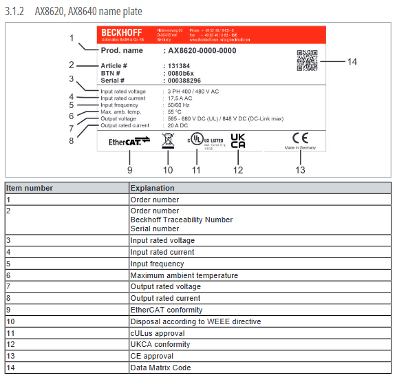
3. Body and nameplate information
All modules come standard with a seven segment digital tube status display screen; The nameplate indicates the model, serial number, rated voltage/current, frequency, temperature, certification, QR code, place of origin, and various compliance labels (CE, cULus, UKCA, WEEE, etc.).
4. Standard/optional features
TwinSAFE Integrated Security: Two Level Configuration
Basic version: Supports STO and SS1 safe stop, meets Cat 4/PL e/SIL 3 requirements;
Advanced Safe Motion Edition: Supports more than ten safety sports functions such as SLS, SOS, SDI, SBC, etc., with the same safety level.
Encoder interface: Supports OCT single cable technology, EnDat 2.2/3, BiSS C, TTL, SinCos and other mainstream protocols, can be connected to main/auxiliary encoders, compatible with linear motors and third-party motors.
Hardware interface: Integrated EtherCAT bus, digital IO, motor power interface, brake, temperature detection, external braking resistor interface.
5. Core product features
High dynamic response: relying on EtherCAT+distributed clock, with a minimum cycle of 62.5 μ s;
Common DC bus architecture: AX Bridge enables quick and tool free interconnection between modules, facilitating energy exchange and reducing energy consumption;
Motor adaptation: Supports Beifu synchronous motor, linear motor, and can also be compatible with third-party motors such as asynchronous and torque;
Cable specifications: Standard OCT single cable solution, with a maximum length of 100m for a single motor cable; the total length of the system bus is limited by topology and reactors.
Core technical parameters
1. Environmental conditions
Working temperature: 0~40 ℃; Power reduction is required above 40 ℃;
Storage and transportation temperature: -25~+55 ℃, temperature change rate ≤ 20K/h;
Relative humidity: 5%~95%, no condensation;
Installation altitude: No capacity reduction within 1000m, 1% capacity reduction every 100m from 1000m to 3000m;
Mechanical performance: compliant with EN 60068, vibration resistance, 5G impact resistance;
Protection level: IP20 for the entire machine, only used inside the control cabinet.
2. Electrical parameters
Grid adaptation
Single phase: 100-240V AC;
Three phase: 200~480V AC;
AX8600 DC model: 120~680V DC.
DC bus: normal 565-680V, peak value up to 848V;
Each module has clear specifications for rated current, peak current, internal capacitance, loss power, braking power, and minimum braking resistance;
24V control power supply: nominal 24VDC (± 10%), with a total power supply limit of 20A for the entire module.
3. Size and weight
Distinguish three types of dimensions: narrow body (AX8108/AX8206/AX8600/AX8620/AX8810), wide body (AX8118/AX8128/AX8640), and combination module (AX85xx), and label installation openings, external dimensions, and individual weight.
4. EMC and Compliance
Electromagnetic compatibility: EN 61800 series, industrial C3 level, optional filter can be upgraded to civilian C2 level;
Certification: CE, cULus, UKCA, EAC, compliant with EU directives such as low voltage, EMC, RoHS, WEEE, etc.
Transportation, storage, and capacitor activation
Transportation: Original packaging must be used to avoid strong impact and severe temperature differences; The stacking height is limited (ordinary modules can have up to 8 layers, and combination modules can have up to 3 layers).
Long term storage:
Storage<5 years: Normal power on is sufficient;
Storage * * ≥ 5 years * * (shortened to 3 years when the environment is greater than 25 ℃): Capacitor activation must be performed – connect the main power and run for 60 minutes without load to restore capacitor performance.
Condensation treatment: When condensation occurs due to temperature differences, let it stand until completely dry before powering on to prevent short circuits.
Mechanical installation
1. Installation prerequisites
The cabinet installation plate adopts galvanized conductive plate to ensure grounding and EMC;
The module must be installed vertically, with ventilation space reserved above and below to ensure heat dissipation;
All installation screws have a specification of M5 and a tightening torque of 6Nm; the grounding nut has a torque of 2.7Nm.
2. Installation process
Prefabricate and install the base plate according to the unified hole position, compatible with the entire series of modules;
First, install the power module, and then arrange the axis module and capacitor module in descending order of current (the capacitor module has the best effect when adjacent to the power module);
Using AX Bridge spring quick connectors to achieve bus, 24V, and bus interconnection between modules, tool free docking;
Modules are connected through grounding hooks to form equipotential bodies.
3. Space and heat dissipation requirements
Reserve ventilation gaps around the module and prohibit blocking the air ducts; Extra ventilation inside the cabinet is required in high-temperature environments.
Electrical installation (key specifications)
1. Overall wiring principle
Separation of strong and weak electricity, all use shielded cables, single ended shielding layer/standardized grounding;
Strictly follow the wiring sequence: ground first → connect the signal line and motor line → finally connect the main power;
All terminals are selected according to wire diameter and follow the corresponding tightening torque.
2. Grounding system
Protective earth (PE): The cross-sectional area of the main grounding wire is ≥ 10mm ², and all modules and cabinets have a single point equipotential;
Functional: Ensure EMC and anti-interference, strictly prohibit virtual connection or series connection;
The system has a potential of 0V and PE, which complies with the EN 60204 PELV specification.
3. Detailed explanation of various interface wiring
Main power interface: distinguish terminal definitions for single-phase/three-phase/DC models, and adapt to different wire diameters and plugs;
External braking resistor: The original terminal is short circuited by default (using built-in braking), and the external resistor needs to be disconnected and matched with the resistance value and power;
DC bus: AX Bridge interconnection, external third-party DC bus crossing is prohibited;
EtherCAT bus: standard RJ45 interface, serial topology, network cable up to 100m in length;
Encoder interface: divided into dual D-sub and single D-sub specifications, with clear definitions for each pin of EnDat/BiSS/TTL/SinCos. The maximum output of a single interface is 250mA;
Motor interface: integrates power lines, brake pads, temperature sensors, OCT signals, and distinguishes plug specifications for different models;
Digital IO: Normal IO and TwinSAFE safety IO have different pins and filtering times, with a safety IO response time of 4ms.
4. Leakage current and selection of leakage protectors
The servo has inherent leakage current, and A/AC type leakage protection is prohibited. B-type (AC/DC universal) must be used, with a rated operating current of ≤ 300mA. The manual provides reference values for the maximum leakage current of each module at different voltages.
5. Grid adaptation
Support TN and TT grounded power grids; IT、 Isolation transformers must be installed to isolate non grounded power grids such as Delta, and wiring topology diagrams for different power grids must be provided.
6. Fuse/Circuit Breaker Configuration
There are two selection schemes for CE standards and UL standards:
Main circuit: distinguish between gG fuses, C-characteristic circuit breakers, and UL Class J fuses;
24V control circuit: Unified standard 20A protection;
Provide the maximum short-circuit withstand current (SCCR) corresponding to different modules.
7. Cable length limit
No incoming reactor: The maximum length of a single motor cable is 25m, and the total length of the system bus is ≤ 300m;
Matching with incoming reactor: The maximum length of a single motor cable is 100m, and the total length of the system bus is ≤ 500m;
Extra long cables require manual input of actual length in TwinCAT drive parameters.
System planning and supporting accessories
1. System capacity calculation
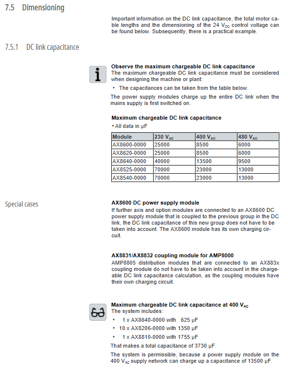
DC bus capacitor total capacity verification: The maximum total capacitance supported by different power modules is different, and the entire set of capacitors must not exceed the limit;
24V control power supply power accounting: calculate the total current of all modules and motor holding brakes, and reserve margin;
Selection of motor current and simultaneous coefficient, with calculation examples attached in the manual.
2. Standard/optional accessories
Braking resistor: two types: internal/external, divided into standard type and IP65 protection type;
Incoming reactor: suppresses current spikes and voltage drops;
EMC filter: adapted to different electromagnetic environments of C2/C3;
Specialized connection cables, DC link interconnection lines, isolation transformers, etc.
Debugging, operation, and daily maintenance
1. Check before powering on
Review all mechanical installation, wiring, and grounding;
Insulation testing and withstand voltage testing must disconnect all module connections to avoid equipment damage;
Check that the emergency stop and safety circuit are intact.
2. Debugging process
Use TwinCAT+TwinCAT Drive Manager 2 for configuration: bus scanning, module configuration, motor parameter input, encoder tuning, and functional testing.
3. Operation monitoring
Real time viewing of status through module digital tube and TwinCAT: EtherCAT communication, bus voltage, shaft status, safety circuit, fault codes.
4. Daily maintenance
The equipment body is exempt from daily maintenance;
Regularly remove dust, prohibit water washing, high-pressure air blowing, and corrosive cleaning agents;
Long term shutdown is performed periodically to activate capacitors.
Shutdown, disassembly, and scrapping
Shutdown and disassembly: Normal shutdown → Cut off the main power → Wait for 30 minutes to release the high voltage → Remove the wires and modules in sequence;
Scrap disposal: Classify and recycle electronic waste such as metals, circuit boards, cables, batteries, etc. according to the WEEE directive, and all regions must comply with local regulations.
Troubleshooting (core phenomenon)
Digital tube error, EtherCAT communication abnormality: check bus wiring, terminals, module configuration;
Overvoltage/undervoltage: Check the input power grid, DC bus, and braking circuit;
Motor cannot run: Check the power line, encoder, brake, and safety circuit (STO);
Overload/Overheating: Check motor parameters, load, and ventilation environment;
Encoder malfunction: Check wiring, protocol matching, and cable length.