Basler BE1-50/51B-255 overcurrent relay
Chapter 1 Product Overview, Core Features, and Replacement Adaptation
1. Product positioning
Single phase microprocessor type non directional overcurrent relay, integrated with 51 time limit overcurrent, 50-A instantaneous overcurrent, and 50-B instantaneous (HLT specific) triple protection components, adopts CT self powered design, does not require external operating power supply, perfectly replacing the old Westinghouse CO-2/5/6/7/8/9/11 electromagnetic relay.
2. Core standard functions
Three stage protection: time limit 51, two independent instantaneous 50A/50B;
HLT hot line hanging function: After the panel switch is turned on, the 50-B contact is connected in parallel with the main tripping circuit, which is used for forced tripping of the line maintenance hanging;
Dual reset mode options: instantaneous reset, integral reset (simulating electromagnetic disk reset characteristics for easy coordination of upper and lower level protection);
Hyperbolic library switching (onboard dialing): ABB CO curve/GE IAC curve, while supporting BS142 British standard curve;
Instantaneous component delay options: 50-A with 0ms no delay/100ms fixed delay, 50-B with fixed no delay;
Panel direct reading setting: no conversion required for current gear and time dialing;
Gravity lock fault indicator light, power failure does not lose fault indicator, manual reset;
Manual trip socket on the front panel, without the need for external signals to directly verify the trip circuit;
Low CT load, anti harmonic, small transient exceedance, high accuracy, built-in continuous automatic calibration.
3. Hardware selection and limitations
Current input: 5A CT standard specification;
Double instantaneous simultaneous action constraint: Two instantaneous triggers require at least 2A input current, and only a single channel setting value lower than 2A is allowed;
Applicable scenarios: Distribution network feeders, transformers, motor phase to phase/ground overcurrent protection, can be coordinated with reclosing for protection coordination calculation.
Chapter 2: All controls and indicator lights for panels and circuit boards
(1) External operating components on the front panel
51 time limit setting
TIME PICKUP: integer+tenth knob, continuous setting from 0.5 to 15A;
TIME DIAL: Time multiplier 0.0~9.9;
CURVE curve selection knob: 9 types of inverse time limit+1 segment of fixed time limit;
50-A instantaneous setting: TENS+UNITS dual knobs, 1~99A;
HLT function
HLT toggle switch (on/off)+HLT neon indicator light (lit when there is a trip voltage);
Test socket: TIME manual trip, INST manual trip, insulation jumper short circuited to simulate outlet action;
Fault target light: TIME (51 action), INST (50-A action), gravity latch, equipped with RESET reset button;
Dual color ACTIVE/PICKUP running light: green light above 0.5A is normal; When the current exceeds 51, the starting value turns red.
(2) Hidden control on the top of the bracket (relay needs to be removed), 50-B instantaneous setting knob, independent gear, HLT function dedicated instantaneous component.
(3) Internal DIP SW3 on Motherboard (Core Configuration Switch)
SW3-1: 50Hz/60Hz system switching;
SW3-2:50-A instantaneous 0ms/100ms delay;
SW3-3: Curve library switching (OFF=ABB CO/ON=GE IAC);
SW3-4: Reset mode (ON=Integral Reset/OFF=Instantaneous Reset);
SW3/5、 6: Reserved unused.
(4) Onboard jumper J1/J2 control fault light action current:
2-3 short circuit: 80~200mA can light up (conventional switchgear);
1-2 Short circuit: 0.9~2.25A high threshold (large capacity trip coil).
Chapter 3: Functional Principles of the Whole Machine
1. Hardware signal link CT secondary current → internal power CT (self powered by the whole machine)+signal CT → signal conditioning and scaling → ADC analog-to-digital conversion → microprocessor operation, independently calculating 51 time limit, 50A/40B instantaneous three sets of criteria.
2. The self powered motor system does not require an external DC/AC power supply, and the CT induced current is rectified to supply power to the entire machine; When the current is below 0.5A, the MCU will sleep and the ACTION light will turn off; Wake up and run at ≥ 0.5A.
3. The 51 time limit protection logic starts timing when the collected current exceeds the PICKUP startup value, and accumulates delay according to the selected curve formula; In the integral reset mode, the fault disappears and the timer will not be immediately reset. Simulating the attenuation characteristics of electromagnetic disks is crucial for the coordination of upper and lower level protection.
General formula for tripping:
\(T_{Trip}=\frac{A D}{M^ {N}-C }+B D+K\)
Integral reset formula:
\(T_{Reset}=\frac{R D}{M^ {2}-1 }\)
D=time dip code, M=current multiple, A/B/C/N/K/R are fixed constants corresponding to the curve.
4. Two way instantaneous logic
50-A: Conventional phase to phase short circuit protection, optional 100ms delay to avoid excitation inrush current;
50-B: Only for HLT hanging use. After the switch is closed, the contacts are connected in parallel to the main trip circuit for maintenance and forced disconnection;
If the current exceeds the corresponding INST gear, it will immediately exit without any inverse time delay.
5. Output and indication
Independent normally open trip contacts: 51, 50-A, 50-B three sets of outlets;
The fault light is only configured for 51/50-A, and there is no indicator light for 50-B;
When the bracket is pulled out, the CT terminal automatically shorts to eliminate the risk of open circuit and high voltage.
Chapter 4 Installation, Wiring, and Maintenance
1. Mechanical installation standard plug-in S1 rack, which can directly replace the Westinghouse CO relay bracket; Half embedded/protruding installation, with a total weight of 2.77kg; no installation angle limitation. 2. Wiring diagram
CT AC input: single-phase current input at terminals 8 and 9;
DC trip circuit: 125V standard control voltage, 51, 50A, 50-B independent trip bus;
Typical wiring of HLT switch parallel trip circuit;
Schematic diagram of external reclosing coordination, accompanied by multiple fault reset time calculation cases.
3. Installation precautions
Adjusting the current knob with electricity may cause accidental tripping;
The withstand voltage test must disconnect the CT by pulling out the relay;
The whole machine is independently grounded;
4. Maintenance and Storage
No regular maintenance, only annual full functional verification;
Idle spare parts are powered on for 30 minutes every year to extend the lifespan of electrolytic capacitors.
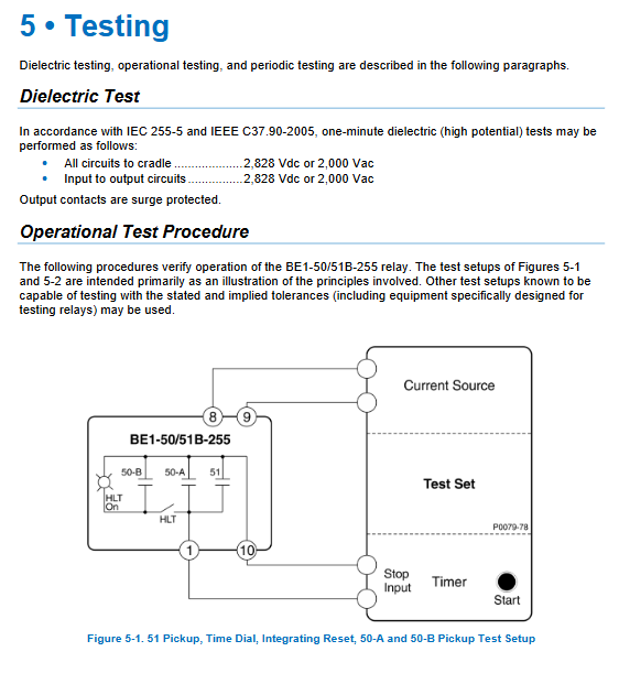
Chapter 5 Standardized Whole Machine Testing Process
Equipped with dedicated current test source and timer, divided into seven testing items, each with a given standard error range:
51 time limit startup test: Verify the startup currents of 0.5A and 2.2A with an error of ± 5%;
Time dialing accuracy test: Fixed current multiple measured tripping time, allowable comprehensive deviation;
Integral reset characteristic test: Simulate multiple overlapping faults and calculate the remaining trip time;
50-A instantaneous setting: 1A and 8A calibration action current;
50-B instantaneous (HLT) test;
Fault target light threshold test, replace jumper to verify action current;
HLT tagging function, manual trip socket verification on the front panel;
Mandatory requirement for testing: Power off for sufficient time before each test to clear the integration timer.
Chapter 6: Complete Electrical and Mechanical Specifications
1. Protection accuracy parameters
51 Start: Action 95% rated, return 95% start value;
Instantaneous component 1~99A continuously adjustable, with an action error of ± 2%;
Delay accuracy: standard curve ± 2 cycles+2% reading;
CT continuous current carrying capacity of 14 A (45 ℃), high temperature derating;
CT load is extremely low, with strong harmonic suppression capability and transient exceeding<10%.
2. Contact capacity: AC 120V, long-term 7A; DC 250V, short-term 30A (0.2s), inductive load breaking is only 0.3A.
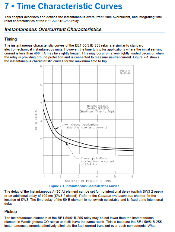
3. Environment and certification work -40~+70 ℃, anti vibration impact, passed IEEE relay protection full set of surge, static electricity, RF tests. Chapter 7 Protection Characteristic Curve (Core Setting Tool)
Two major curve libraries
Library 1 (SW3 OFF): matches ABB CO-2/5/6/7/8/9/11;
Library 2 (SW3 ON): matches GE IAC 55/66/51/53/77;
General: BS142 British standard B/C curve, 0.1~9.9s independent definite time F curve;
Curve types: short inverse, long inverse, definite time, moderate inverse, standard inverse, severe inverse, extreme inverse, I ² t curve;
Provide all curve vector diagrams and A/B/C/N/K/R constant tables for each curve, for use in tuning software calculations;
Integral reset dedicated curve, used for coordinating calculation of multiple levels of reclosing protection.