Basler BE1-FLEX Integrated Protection Control System
Product Overview (Introduction)
1. Product positioning
Modular multifunctional digital protection device, suitable for almost all primary power equipment such as feeders, transformers, generators, motors, busbars, capacitors, and grid connection points, supports single/multiple circuit breaker automation, and takes into account protection, measurement, alarm, waveform recording, and event recording.
2. Core hardware expansion capability
Simulated acquisition: up to 28 CT and 16 VT channels;
Switching quantity: 72 inputs, 48 outputs;
Auxiliary acquisition: 4-20mA/0-10V analog quantity, RTD temperature, 50/100mV shunt DC acquisition;
Hardware can add or remove boards on site without the need to replace the entire machine, supporting on-site/renovation/new projects.
3. Human Machine and Communication
7-inch custom touch screen HMI;
Local USB, rear copper/fiber optic Ethernet RS485;
Synchronous clock: NTP+IRIG-B, capacitor+battery dual backup (battery life of more than 5 years).
4. Record storage capacity
COMTRADE standard fault recording (30 million+data points);
8000 SOE event sequence records;
Safety audit logs, load curves, cumulative transformer faults, power quality, diagnostic logs, etc.
5. Complete List of Protective Components (Standard Power ANSI Number)
Impedance class: 21P phase to phase distance, 21N grounding distance, 40Q reactive demagnetization, 40Z impedance demagnetization, 78OOS step loss, 78V phase jump
Excitation/Overvoltage Category: 24 Overexcitation, 25 Synchronization Check, 25A Automatic Synchronization, 27 Undervoltage, 59 Overvoltage, 47 Negative Sequence Voltage
Current protection: 37 instantaneous undercurrent, 46 negative sequence overcurrent, 50 instantaneous overcurrent (phase/ground/SEF), 50BF circuit breaker failure, 51 inverse time overcurrent, 51TF fault accumulation, 76 DC overcurrent
Power category: 32 active power (reverse power/over power), 55 power factor
Grounding/Differential: 64G stator grounding, 87 phase to phase differential, 87FB flux balance differential, 87N neutral differential
Thermal protection: 49RTD resistance temperature measurement, 49TC thermal curve (motor/transformer overload thermal model)
Control category: 62 logic timers, 66 motor start times, 60FL fuse breakage, 79 reclosing, 86 virtual locking, 101 circuit breaker control, 52TCM trip circuit monitoring
Custom protection: Four arithmetic operations can be configured to customize protection logic
6. Software core BEST logic ™ Plus
Drag and drop programmable logic, simulating traditional relay schematic configuration, with all protections, inputs and outputs, and alarms freely linked.
7. Model Configurator Style Configurator
Generate complete model codes through slot board selection, distinguishing chassis, power supply, analog board, IO board, communication board, protocol package, and terminal types.
Quick Start
Equipment acceptance: check the model and appearance for damage; Idle equipment can be powered on for 30 minutes every year to extend the lifespan of electrolytic capacitors.
BESTCOMSPlus software installation requirements
Operating system: Win7 SP1/8.1/10/11; Minimum 2.0GHz processor, 1G memory, 200MB hard drive; Installation requires administrator privileges, pre installed NET framework.
Connection process: Install software first → USB connect device → Power on → Software creates a new USB connection → Install/download settings and logic.
Basic programming example (instantaneous grounding of feeder 50+reverse phase overcurrent of 67):
Download device data → Configure primary circuit CT/VT ratio → Map hardware IO → Enable protective components → Logical wiring → Save and upload device.
Install Mounting
Chassis specifications: K-type vertical standard S1 cabinet with openings, can be installed at any angle (screen does not rotate); Install bolts with a torque of 20-25 in lb.
Hole drawing: dimensions of the front and side of the whole machine, and dimensions of the panel holes.
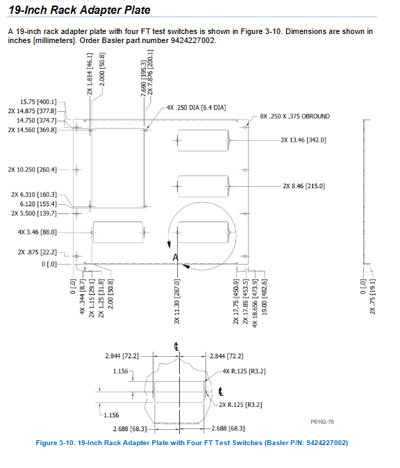
Adaptation adapter board (compatible with old relay cabinet renovation): GE S2, ABB FT21/FT31, GE M1/M2, Multilin 345/745, 19 inch rack, rotating telescopic installation kit, corresponding material number provided.
Hardware Configuration
1. Definition of chassis slots (fixed order)
Slot 1: Power board (only compatible with power supply); Slot 2: Dedicated for communication board; Slot 3-7: IO/analog board; 4/5/6/7 supports analog acquisition boards.
2. Various board specifications
Three types of power boards: 48/125Vdc+120Vac, 250Vdc+240Vac, 24Vdc; Comes with RS485 interface.
Communication board: Copper network (single/dual), fiber optic (single/redundant), supports PRP/HSR redundancy, RJ45/LC fiber optic port, protocol package 1 (Modbus/DNP), package 2 (plus IEC61850).
Analog acquisition board: 4/7 channel CT, 4 channel VT, CT+VT composite board, supporting SEF high-sensitivity grounding acquisition.
IO auxiliary board: switch input/output, 7-channel RTD temperature measurement, mV DC shunt acquisition.
3. Wiring torque specifications
Analog board crimping terminals: 8-11 in lb, supporting 2 pieces of 10AWG;
IO spring terminal: 4.4~5.3 in-lb, wire nose 8~10mm stripped wire;
All cables use 75 ℃ copper wires.
4. Card replacement process
Power off to release ESD protection, remove panel/backboard, and automatically recognize the same model of board when powered on; After replacing the hardware, it is necessary to update the hardware instance and verify the settings in the software.
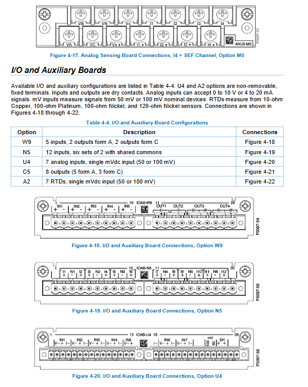
Typical Connections
Covering feeder lines, generator differentials, transformer differentials, flux balance differentials, three-phase VT (3-wire/4-wire/single-phase PT), CT currents, 4-20mA/0-10V transmitters, two/three wire RTDs, and standard wiring for DC splitters; The minimum requirement for CT incoming line is 12AWG, and the entire machine is reliably grounded.
Application Templates
Basler prefabricated set of fixed value templates: feeders, transformers, generators, motors, and grid connection points, including a single line diagram, complete logic, and protection settings, can be directly imported into BESTCOMSPlus for modification and use.
Template usage process: Open the template → Match local hardware slots → Configure CT/VT/system frequency → Enable protection, configure logic, and upload devices.
Virtual circuit function: Multiple sets of CT vectors are stacked without the need for additional transformers, suitable for current summary measurement/protection on the high and low voltage sides of the main transformer.
Human Machine Interface (HMI)
Front panel hardware: 7-inch touch screen, USB-C local port, power/fault/size alarm/trip LED indicator light.
Screen functions: customizable main screen (single line diagram, circuit breaker button, status indicator), target/alarm summary, real-time measurement, fault recording SOE、 Parameter settings.
HMIC Editor: Customize the interface through SVG images, configure circuit breaker status, indicator lights, shortcut tags, pop-up permissions, and support SBO selection and control operations (anti misoperation, requiring secondary confirmation).
Permission and Backlight: Adjustable Backlight, Sleep Timer; Language switching between Chinese and English; All modifications require corresponding permission passwords.
Web HMI (BEST netPlus): IP access, functions identical to the local touch screen, and can independently disable web services.
BESTCOMSPlus upper software
Software functions: graphical constant value editing, drag and drop logic BEST logic Plus, constant value file (bst4), logic file (bsl4) management, COMTRADE waveform export (with BESTdata analysis software), device firmware upgrade, multi device constant value comparison.
Communication methods: USB local, Ethernet remote; Support batch upload/download of fixed values, security configurations, and fault reports.
Verification function: The software automatically recognizes out of range error settings, locates error items in pop-up windows, and cannot download devices for unqualified files.
Firmware upgrade: After uploading the firmware package, the device will automatically restart. After the upgrade, the default value will be loaded, and the user project needs to be re uploaded.
Security Permissions Security
7-level independent access permissions (read, control, write fixed values, logic editing, firmware upgrade, administrator, security audit), independent passwords at all levels, not included in each other.
Port permission control: USB, Ethernet RS485、 The local touch screen can be separately set with no login permission/password permission, and will automatically log out and lock when idle.
User management: default account a/admin, supports adding new users and password validity period; All login/operation records are stored in the security log (with a maximum of 200 loop covers).
Restrictions: If the entire machine administrator password is lost, it can only be returned to the factory for repair, and there is no on-site reset method; Security configuration independent. bss4 file storage.
Power System Configuration
The core primary side parameter configuration module includes:
Circuit settings: CT/VT ratio, secondary rated current/voltage, phase sequence ABC/AC, VT wiring (4Y/3 Δ/single-phase);
Sequence component calculation: positive/negative/zero sequence voltage and current, direction discrimination (maximum torque angle MTA, blocking angle, load intrusion locking anti misoperation);
Circuit breaker monitoring: opening and closing counting, fault breaking capacity accumulation, trip circuit monitoring 52TCM;
Motor resources: FLA full load current, start stop current criteria;
RTD/analog/shunt input grouping, range calibration;
Load statistics, power quality (voltage fluctuations, harmonics), multiple setting groups (4 sets of fixed values SG0~SG3, with logic automatic switching, suitable for winter and summer/light heavy load scenarios).
Equipment information, clock, constant value group
Equipment information: serial number, model, firmware, IP address, Style hardware model, Ethernet DHCP/static IP, NTP server configuration;
Timing system: IRIG-B, NTP, DNP3 three source timing, real-time clock backup battery replacement steps;
4 sets of fixed value groups: discrete/binary logic switching, automatic switching according to load current, used for differential protection settings during cold start, heavy load, and system maintenance.
Detailed explanation of the complete set of protection, control, and recording components
Each type of ANSI protection has an independent chapter and a unified structure: functional principle, fault recording configuration, logic input and output, setting parameters, timing curve, interlocking conditions (60FL voltage loss interlocking, external block logic), covering all device functions such as distance, differential, excitation, thermal protection, motor, reclosing, circuit breaker failure, etc.
Events, tests, troubleshooting, specifications
Recording function: SOE event sequence, fault report, chart recorder, load curve, fault accumulation;
Test: complete testing process including factory acceptance, commissioning test, and periodic test;
Troubleshooting: communication abnormalities, hardware alarms, protection misoperation/refusal, IO fault location;
Whole machine electrical, environmental, protocol EMC、RoHS、 Complete specifications and parameters for maritime affairs.