Operation Manual for Basler BE1-32R/BE1-32O/U Direction Power Relay
General information (product positioning, seven major application scenarios, model code, complete electrical specifications)
1. Core positioning of the product
Two solid-state relays calculate the active power P=EIcos θ by collecting system voltage and current, and determine the power flow direction. They are used for over power, under power, and reverse power protection in single-phase/three-phase power grids; BE1-32R only detects unidirectional over/reverse power; BE1-32O/U integrated dual detection of over power and under power; It is not recommended to use it under the condition of power factor<0.1.
2. Seven typical industrial application scenarios
Anti motor operation (reverse power protection)
The synchronous generator loses its prime mover and is dragged by the power grid to become an electric motor, which can damage the steam turbine, diesel engine, and gas turbine; The table shows the setting intervals for reverse power protection of different prime movers: 0.2~2% rated kW for water turbines, 0.5~3% for steam turbines, up to 25% for diesel engines, and up to 50% for gas turbines; Configurable delay to avoid transient errors in grid connection.
Distributed parallel control (cogeneration)
Automatically start the generator when the incoming power of the power grid exceeds the limit; The power grid will automatically shut down when the power is too low, and BE1-32O/U will simultaneously achieve over/under generation monitoring.
Generator overload protection
Power exceeding the limit triggers an alarm, load shedding, and starts the standby unit.
Contact transformer/distribution network protection
Monitor the power flow of two main transformers to prevent reverse power transmission and overload.
Unit delay electrical tripping
When a large steam turbine unit trips due to non electrical faults, the circuit breaker is delayed and the residual steam in the pipeline is discharged.
Circuit breaker position monitoring
After the incoming switch is disconnected, the power is reversed and the interlocking circuit is opened for isolation.
Reactive power (Var) monitoring
By adjusting the phase shift of the collected voltage by 90 °, the active power relay is modified for reactive power flow monitoring to identify generator demagnetization conditions.
3. Model and style coding rules
The complete identification of the device consists of the model and style number, printed on the panel, plug-in base, and inside the chassis; Style code segmentation definition: collect input type, power measurement range, output contact type, power supply specifications, timing type, action indicator, auxiliary output, installation method, etc., with code disassembly examples attached.
Collect 5 types of inputs:
A: Single phase voltage+single phase current (no phase sequence sensitivity)
B/V: Line voltage+single-phase current (60Hz B, 50Hz V, phase sequence sensitive)
C: Three phase line voltage+single-phase current (no phase sequence sensitivity)
D: Three phase phase voltage+three-phase current (no phase sequence sensitivity)
E: Two phase current+three-phase line voltage (two watt meter method, phase sequence sensitive)
4. Complete set of electrical performance specifications
(1) Current/voltage acquisition circuit
Adapt to standard 5A secondary CT; collect ranges in multiple stages, distinguish between continuous, 1-minute, and 1-second short-term overload currents;
The voltage is taken from PT secondary, with a continuous withstand voltage of 150% of the rated voltage, and the collected load is less than 1VA;
Detailed table of CT circuit impedance (Burden) for each gear, used for CT secondary load verification.
(2) Action indicator (Target)
Optional built-in driver/current driven type; Current driven type with a minimum operating current of 200mA, electronic latch LED, and manual panel reset; Turn off the power and restore the locked state when powered on.
(3) Output contact capacity
Distinguish between AC resistive, DC resistive, and inductive load rated currents, support normally open NO/normally closed NC/SPDT auxiliary contacts, and power status monitoring contacts.
(4) Power supply
4 types of power supply specifications (24Vdc/48Vdc/125Vdc&120Vac/250Vdc&240Vac), indicating power consumption and input voltage range; The minimum starting voltage of R-type 24Vdc is 14V, and it can be as low as 12V after operation.
(5) Action accuracy
Single phase: When PF=1, the error is ± 2% of the set value; ± 5% when 0.5<PF<1;
Three phase: ± 2% when PF=1, ± 5% when 0.5<PF<1;
Return value: 95% reliable return of action value.
(6) Temporal characteristics (three temporal modes)
Instantaneous type: Under 2 times the operating power, 60Hz response<80ms, 50Hz<100ms; Under power instantaneous response is faster (< 50ms@60Hz );
Definite Time: 0.1~9.9s (x 0.1 magnification), 1~99s (x 1 magnification), 00 gear=instantaneous; Timing error ± 5% or 50ms;
Inverse Time: Only available for over power, multiple sets of standard inverse time curves, panel dial 01-99 to select the curve.
(7) Power setting range
The table lists all high and low range power settings (0.5W~6000W range) for single-phase/three-phase, 120V/208/240V.
(8) Environmental and Mechanical, Type Testing
Temperature: Operating -40 ℃~+70 ℃; Storage -65 ℃~100 ℃;
Anti vibration: 10-500Hz 2G three-axis vibration; Impact resistance: 15G three-axis;
Insulation withstand voltage, surge immunity, and radio frequency immunity comply with IEEE and IEC standards;
Weight: S1 shell has a maximum weight of 13.5lb, M1 shell has a maximum weight of 18.5lb.
Front Panel Controls
All tuning components, indicator lights, and reset buttons are concentrated on the front panel, including:
Range switch (high/low power mode);
Overpower dip delay and delay multiplier switch (0.1/1.0);
Overpower gear adjustment knob (Tap);
Underpower potentiometer (10%~95% over power setting);
Two action indicator lights (Over/Under Pickup LED) and power indicator light;
Action indicator reset button;
Output test hidden button (non-metallic rod manually triggers verification output);
The gear power comparison table is printed on the panel.
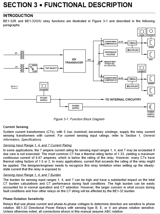
Functional principle explanation
Signal acquisition process
CT/PT collects current and voltage and sends it to the internal kW multiplication converter to calculate the actual active power. It outputs a DC analog voltage and sends it to the comparator, which compares it with the panel setting threshold to trigger the timing circuit, output relay, and latch indicator.
Phase sequence sensitivity
The B/V/E acquisition method is sensitive to the phase sequence of ABC/ACB, and the wiring must match the phase sequence; There is no phase sequence requirement for A/C/D.
Classification of output circuits
Main protection output: independent contacts for over power and under power;
Auxiliary output: optional NO/NC/SPDT;
Power status monitoring: Contact displacement in case of power loss; Inserting or unplugging the base will result in a short circuit status output.
Power and indicator logic
The whole machine is isolated from a wide power supply and has no polarity; The electronic latch indicator can only be manually reset, temporarily extinguished when powered off, and restored when powered on.
Installation, wiring, maintenance, and storage
1. Installation specifications
Solid state without mechanical structure, no mandatory requirement for vertical installation; Provide three views of the semi embedded and protruding installation hole dimensions and the overall appearance of the S1 and M1 shells; The installation screw specifications and panel opening drawings are complete.
2. Wiring specifications
Main circuit wiring ≥ 14AWG, grounding ≥ 12AWG independent ground wire;
Divided into five categories of drawings: control circuit diagram, internal wiring for 5 types of acquisition, BE1-32R/BE1-32O/U external standard wiring, and on-site wiring diagram for 5 types of acquisition methods;
Before the pressure test, the plug must be unplugged and the core must be extracted to prevent equipment damage; The current driven indicator trip circuit must ensure a current of ≥ 200mA.
3. Maintenance and Repair
No regular preventive maintenance, only complete machine calibration is conducted on a periodic basis;
The circuit board does not support on-site maintenance, and if there is a malfunction, the plug-in core can be replaced directly; Repair requires contacting the manufacturer for authorization;
Supporting dedicated test plug: internal circuit can be verified online without removing the device.
4. Storage requirements
Idle equipment is powered on for 30 minutes every year to extend the lifespan of electrolytic capacitors; The storage environment should be dust-proof and moisture-proof.
Whole machine verification testing process
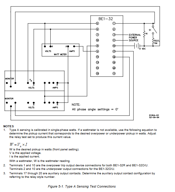
Provide standardized on-site verification steps, with 5 dedicated testing wiring diagrams for collection methods, covering all verification items:
Overpower action/return value verification (unity power factor);
Underpower action/return value verification;
Instantaneous action time test;
Time limited delay accuracy test (separated over/under power);
Verification of over power inverse time limit curve;
Each test provides panel tuning parameters, standard qualified error range, and power conversion formula (different power calculation formulas correspond to different acquisition types).