Basler BE3-25 synchronous check relay
Product application and functional differences between two segmented models
1. Core purpose
BE3-25 belongs to synchronous verification relay (grid connected parallel relay), used for verifying two AC power sources before grid connection. Only when the voltage, frequency, and phase angle are within the set threshold at the same time, the relay output contact is closed, allowing for grid connection; It can monitor the busbar and standby generator, and can also be used for synchronization between two generators.
2. Differences between two model versions
**BE3-25-**4
Basic version: Only simultaneously collect the bus BUS and generator GEN voltage for synchronous comparison;
Synchronous voltage difference setting range: 10%~30% of generator voltage, corresponding to electrical phase angle of 6 °~20 °;
The pressure difference is fixed at 5%, and the repeatability is better than 0.5% of the full range; Typical action time is 500ms.
BE3-25-5
Add Dead Bus function on the basis of all functions of Type 4: only the generator side has power, and the relay can also be closed when the bus loses power, which is suitable for scenarios such as external power outage and islanding start-up of the unit.
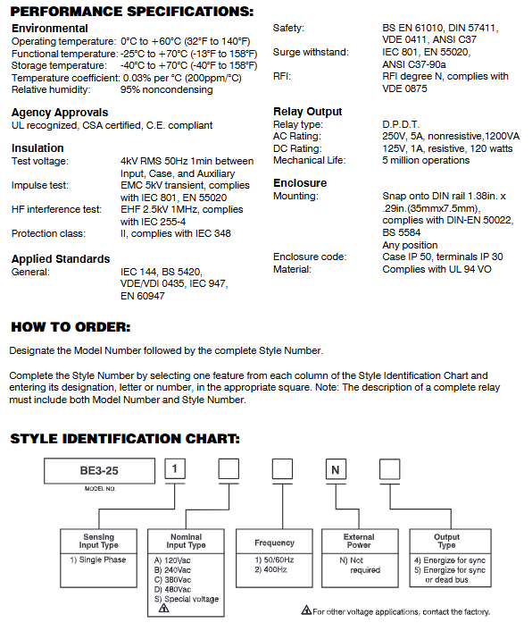
Terminal definition and hardware structure
Terminal arrangement of the body: 14, 11, 12, 22, 21, 24; Functional terminal identification:
3: BUS bus voltage input
4: GEN generator voltage input
2: Power indicator light POWER
SET knob: synchronous differential pressure/phase angle setting knob
The whole machine is installed with DIN rail buckle, with a net weight of approximately 0.6kg (1.32 pounds) and a width of 100mm (3.94 inches).
General Electric Input Specification
Rated input voltage
Standard gears: 120V, 240V, 380V, 480V; Special voltage can be customized to the factory.
Support frequency
50/60Hz power frequency, or optional 400Hz intermediate frequency model.
Input load (Burden)
Generator GEN terminal load<4VA; Bus BUS terminal load<2VA.
Voltage overload tolerance
Long term sustainable withstand 1.5 times the rated voltage; It can withstand 10 times the rated voltage surge in just 3 seconds.
power supply method
The whole machine is self powered and does not require external auxiliary power supply.
Set parameter indicators
Adjustable voltage difference range: 10%~30% of the rated voltage of the generator, corresponding to 6-20 electrical angles;
Fixed hysteresis: 5%;
Repeatability accuracy: better than 0.5% of full scale;
Typical action response time: 500ms.
Output contact performance parameters
Contact type: DPDT double pole double throw
Rated AC load
250V AC,5A, Non resistive load, capacity 1200VA;
DC resistive load
125V DC,1A, Capacity of 120W;
Mechanical lifespan: 5 million actions;
Insulation withstand voltage: 4kV RMS/50Hz withstand voltage for 1 minute between input, shell, and auxiliary circuit;
Impulse withstand voltage: 5kV transient impulse, meeting IEC 801 and EN 55020 electromagnetic standards.
Environment, protection, and electromagnetic compatibility performance
1. Temperature range
Normal operating temperature: 0 ℃~+60 ℃
Functional tolerance temperature: -25 ℃~+70 ℃
Storage temperature: -40 ℃~+70 ℃
Temperature coefficient: 0.03%/℃ (200ppm/℃)
2. Humidity
Relative humidity of 95%, suitable for use in a non condensing environment.
3. Electromagnetic anti-interference
Radio frequency interference RFI level N;
High frequency interference test: 2.5kV/1MHz, in compliance with IEC 255-4;
Meets multiple national electrical safety standards such as BS EN 61010, ANSI C37, VDE, IEC 801, etc.
4. Protection level and material
Shell IP50, wiring terminal IP30;
Flame retardant grade UL94 V0; Protection level II (IEC 348).
5. Installation specifications
Compatible with 35mm standard DIN rails (DIN-EN 50022, BS 5584); It can be installed at any angle without any vertical installation restrictions.
Certification and ordering coding rules
Product Certification
UL certification, CSA certification, CE compliance, meeting the global mainstream equipment access standards.
Order coding rules
Complete device identification=model BE3-25+complete style code (Style Number);
Style code segmentation definition: Input the number of phases, sensing voltage specifications, rated frequency, external auxiliary power supply, output type, and select the corresponding letter/number combination in each column to form the complete model.