ADLINK PCIe – GIE7x Series PCIe x4 Interface GigE Vision PoE+Gigabit Network Image Capture Card
Product model differentiation
Model Network Port Channel ToE (Ethernet Triggered) License Management
PCIe – GIE72 2 Gigabit None None
PCIe – GIE72 PRO 2-channel Gigabit ✅ Support ✅ Support
PCIe – GIE74 4-way Gigabit None None
PCIe – GIE74 PRO 4-way Gigabit ✅ Support ✅ Support
Core hardware specifications and features
Bus: PCIe Gen2 x4 (2.5GT/s), can be inserted into x4/x8/x16 slots; Network card chip Intel I210.
Ethernet: Independent Gigabit Ethernet ports, each with a bandwidth of 1Gbps; Supports Jumbo Frame up to 9KB; Port Aggregation Link Aggregation; Hardware IEEE1588-PTP precise time synchronization.
PoE+power supply (IEEE 802.3at)
Each port has a maximum output of 30W; backward compatible with PoE (IEEE802.3af, maximum 15.4W); automatically identifies PD powered devices.
The power supply voltage output is 50-57V.
Three levels of power supply sources:
PCIe slot only power supply: total PoE budget of 20W;
4-pin Molex 12V external: 61.6W;
6-pin Molex 12V external: 61.6W;
PCIe – GIE74 PRO can connect 4pin+6-pin simultaneously, with a total PoE power of up to 120W.
Improve PoE protection mechanism
Overvoltage OVP 62V, undervoltage UVP 29V; Overcurrent protection (cut off according to the threshold of PoE device class classification); Over temperature protection OTP (configurable high and low temperature thresholds, default high temperature shutdown at 130 ℃, low temperature recovery at 90 ℃).
Port fixed priority: Port1>Port2>Port3>Port4; When the total power is insufficient, priority should be given to ensuring power supply to high priority ports, while low priority ports should be powered off.
The software can individually switch each port PoE, read the voltage, current, power consumption, and device class level of each channel.
The PRO version has two unique features
ToE Trigger over Ethernet trigger: following the GigE Vision Action Command standard; External isolation triggers DI input, the board hardware generates broadcast network data packets, and directly triggers one or more cameras through Ethernet cables; A single Ethernet cable can simultaneously achieve image data, PoE power supply, and trigger signals without the need for additional wiring; Hardware implementation, with fixed triggering delay and no jitter; Support group triggering.
Hardware license management: onboard SHA256 secure EEPROM, software authorization encryption, no encryption dongle required; Software manufacturers can authorize by function to protect intellectual property and prevent piracy.
External trigger input: 4-channel isolated DI trigger input; There is a CN6 socket on the onboard board, and the PRO model can choose a DB-10 external IO socket.
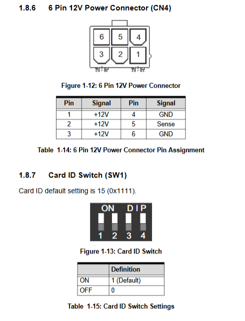
Card ID SW1:4 DIP dip code, set Card ID for multi card system, values 0-15, factory default all ON=15.
PoE hardware switch SW3 (two digit DIP)
Bit1: PoE hardware master switch; OFF=Enable PoE (default), ON=Force all PoE to be turned off;
Bit2: Power on PoE initial state; Power on PoE is turned on when turned off (default), and all power on PoE is turned off when turned on.
Indicator light
RJ45 network port dual color LED: speed indicator, link/activity indicator;
Yellow PoE status LED on the board: corresponding to Port 1-4, lit up indicates that the port’s PoE output is working;
The PCIe link status LED on the board is used to determine the PCIe link Gen1/Gen2 and fault status.
Environment and Machinery
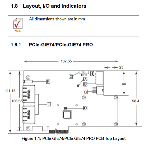
Size: 167.6 mm × 106.6 mm;
Temperature: PoE total power 20W/61.6W Operating condition: 0-70 ℃; Full power 120W (only for GIE74-PRO): 0-40 ℃; Storage -40~85 ℃;
Certification: CE/FCC Class-B, RoHS.
Software system: Windows 7/8.1/10; Supports VC++, C #, VB.net; Smart GigE SDK, PoE power management tool.
Interface Description
RJ-45 Gigabit Ethernet port: transmits images and outputs PoE+power simultaneously; Support automatic recognition of cross/direct network cables.
CN3 (4-pin Molex 12V): External auxiliary PoE power input.
CN4 (6-pin Molex 12V): External auxiliary PoE power input, GIE74-PRO simultaneously connected to CN3+CN4 to achieve a total power of 120W.
CN6 onboard 10pin trigger input socket: 4-channel isolated DI trigger input, isolated common terminal COM_i.
PRO optional accessories: DB-10 IO socket with 4 isolated trigger DI outlets.
Important: The external Molex power supply only provides power for PoE cameras and does not supply the board itself; The main power supply of the board still comes from the PCIe slot.
PoE power management
SDK/Utility can read: total power budget, reserved power, remaining power, real-time power consumption; Each port voltage, current, and PD device classification level.
Port priority is fixed, with Port 1 having the highest priority and Port 4 having the lowest priority; Insufficient power, automatically cut off low priority ports.
The over temperature threshold can be customized by software: high temperature shutdown 80-130 ℃; Restore temperature to 70-120 ℃.
Support reading board temperature and MCU firmware version.
Working principle of PRO version ToE (Trigger over Ethernet)
External isolation DI trigger signal is sent to the board; Hardware detects edges and sends a GigE Vision Action Command broadcast message.
The camera needs to be pre configured with matching ActionDeviceKey, ActionGroupKey, and ActionGroupMask. Only cameras that match the key will respond to the trigger.
Triggering events: start of collection, stop of collection, frame start, transmission start, timestamp reset; The specific behavior depends on the camera firmware.
Advantages: Fixed trigger delay, no software jitter; Implement a complete solution of one Ethernet cable power supply+image+trigger, reducing on-site wiring.
Hardware installation steps
Open box inspection accessories: board body+quick start guide; Pay attention to anti-static operations.
Power off the computer, insert PCIe x4/x8/x16 slots, and screw the baffle in place.
If high-power PoE is required, connect a 4-pin/6-pin Molex 12V external power supply.
Connect the GigE Vision camera to the RJ45 port via Ethernet cable; When external triggering is required, connect the DI trigger cable.
Power on; Install the Intel I210 network card driver and ADLINK Smart GigE SDK into the system.
Attention: You cannot only use the built-in network port driver on the motherboard. You must install the Linghua I210 driver.
Safety points
Be sure to turn off the power when disassembling and assembling the board; PoE output up to 57V high voltage, be careful to prevent electric shock.
PoE system is only for indoor use and cannot be deployed outdoors.
The working heat dissipation temperature of the board is relatively high. Do not touch the metal heat sink to prevent burns.
Do not disassemble and repair on your own; Incorrect replacement of lithium batteries poses a risk of explosion.
Typical applications
Machine vision inspection equipment, scientific research instruments, medical imaging equipment; Multi GigE camera synchronous acquisition; Suitable for visual projects that require PoE to power the camera and reduce wiring; The PRO version is suitable for multi camera synchronized triggering scenes.
Simple distinction from the previous collection cards
Core positioning of board interface type
PCIe 7256/7432 digital IO pure switch IO board, no image acquisition
PCIe 83xx EtherCAT motion control board with a small amount of local IO
PCIe 8560/PXI 8565 PCIe PXI Bridge Remote Expansion PXI Chassis, No Visual Design
PCIe CPL64V Camera Link Interface Image Acquisition Card
PCIe – GIE7x GigE Vision Gigabit Ethernet PoE+Industrial Camera Capture Card