Bonfiglioli ACTION series ACT210 (230V), ACT410 (400V) frequency converter operation manual
Storage and transportation
Storage: Keep the original factory packaging in a dry, dust-free, and low temperature difference environment; Storage without power for up to 1 year. If it exceeds 1 year, it must be powered on for 60 minutes. If it exceeds the deadline, the capacitor needs to be reset and the manufacturer should be contacted; Meets DIN EN 60721 storage standard.
Large item handling (Size7 high-power model): Center of gravity offset, use qualified lifting equipment; Do not stand under suspended objects; Size7 lifting requires the use of M8 casing lifting rings, with a lifting angle of no less than 60 °.
Unboxing: Immediately inspect for transportation damage upon receipt and report the damage to the supplier within 7 days.
Installation in place: Size1-6 manual handling and installation of cabinets; Size7 must be lifted by lifting equipment, only vertical installation is allowed, and horizontal or inverted installation is prohibited.
Scope of Supply
The equipment is divided into Size1/2/3/4/5/6/7, with power ranging from small to large:
Specification, power range, packing accessories
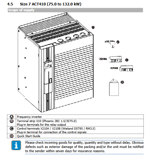
Size1‑2 ACT210 ≤3kW; ACT410 ≤ 4kW frequency converter body, pluggable power terminals X1/X2, relay terminals X10, vertical installation fixed bracket, control terminals X210A/X2210B, quick start guide
Size3‑4 ACT210 4‑9.2kW; ACT410 5.5-15kW frequency converter, X10 terminal, M4 mounting bracket screw, control terminal, quick guide
Size5 ACT410 18.5-30kW frequency converter, X10 terminal, M4 screw bracket, control terminal, quick guide
Size6 ACT410 37-65kW frequency converter, X10 terminal, M5 bracket, control terminal, quick guide
Size7 ACT410 75-132kW frequency converter X10、 Control terminals, quick guide
All terminals are designed to be pluggable for easy wiring and maintenance; Optional communication board, encoder board, and IO expansion board are not included in the standard supply.
Technical data
General environmental parameters
Protection level IP20 (provided that the cover terminal is fully installed);
Temperature: storage -25~55 ℃, transportation -25~70 ℃, operation -0~55 ℃; Power reduction is required for temperatures above 40 ℃; Capacity reduction above 1000m altitude, up to 4000m maximum;
The environment meets EN60721-3-3 3K3; Humidity 15-85% without condensation;
The power grid supports TN/TT/IT power grids; Do not allow corner grounding of TN power grid;
Overvoltage category III, pollution level 2; Maximum short-circuit withstand current 5kA;
Function: V/f control, sensorless vector control, magnetic field orientation control with encoder; Positioning, lifting and braking control, S-curve acceleration and deceleration, PI process controller, master-slave communication, 4 independent parameter sets, fault memory, PC debugging software.
Electrical specifications for control terminals
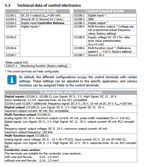
X210A:+20V output maximum 180mA, multiple digital inputs; Some terminals support high-frequency pulses up to 150kHz;
X210B: Digital output (maximum 40mA); Multi functional output (analog/PWM/frequency output); +10V reference power supply (4mA); Multi functional analog input 0-10V/0-20mA;
Relay X10: Switching contact, AC240V 5A connection capability.
Power meters of various models
ACT210:230V,0.55‑9.2kW;
ACT410:400V,0.55‑132kW; Provide rated output current, 60 second long-term overload, and 1 second short-term overload current; Minimum and recommended resistance values for braking resistors; Enter fuse specifications; Weight and external dimensions; The switching frequency can be selected from 2/4/8/12/16kHz. The higher the switching frequency, the smaller the allowed output current, and a derating is required.
Derating Curve for Capacity Reduction
When the ambient temperature exceeds 40 ℃, the output capacity decreases by 2.5% for every 1K increase, with an upper limit of 55 ℃;
For every 1000m increase in altitude, the output decreases by 5%;
The bus voltage is higher than 400V, and the output current decays with the increase of voltage.
Mechanical installation
Installation requirements: can only be installed vertically and upright; Prohibition of horizontal, inverted, and hoisting; IP20 is only available inside the control cabinet; Install to prevent screws, iron shavings, and foreign objects from falling into the interior of the equipment, which may cause short circuits and fires.
Cooling air duct: the bottom of the cold air equipment enters and the top exits; Reserve ventilation gaps up and down, with a minimum of 100mm for small models and a minimum of 300mm for Size7 high-power models. Do not block the fan inlet and outlet; Stay away from dust, oil, corrosive gases.
Provide the overall dimensions, openings, and screw specifications for the fixed bracket in size: M4, M5, M8 bolts, with different installation bracket styles for different power levels.
Electrical installation
Important: After power failure, it is necessary to wait for the discharge of the DC bus capacitor to be completed. Size1-7 must wait for at least 3 minutes before proceeding with the wiring operation; Must be a certified electrician for operation.
7.1 EMC Electromagnetic Compatibility Specification
The power board and reactor are installed on a galvanized metal backplate; Ensure proper equipotential grounding of the system;
Power cables and control signal cables are physically separated and routed;
It is recommended to use shielded cables for motor and braking resistor cables, with PE connections at both ends of the shielding layer; single ended grounding is recommended for analog signal cables;
When using an ungrounded power grid, it is necessary to remove the internal Y capacitor of the equipment;
Leakage protection RCD: B-type full current sensitive leakage protector must be used for three-phase systems. The PE ground wire of this equipment will have a DC component, and A-type RCD is unreliable.
7.2 Terminal Block Diagram
X1: Main power input L1/L2/L3, DC bus+/-;
X2: Motor U/V/W, braking resistance Rb1/Rb2;
X10: Relay output;
X210A/X210B: All digital and analog control IO.
7.3 Optional Hardware Modules
KP500 operation panel;
CM communication module: RS232/485, CANopen, Profibus DP, EtherCAT, Profinet;
EM expansion module: encoder interface, rotary transformer, IO expansion, system bus module; Power on automatic recognition insertion module.
7.4 Cable selection
Specification for selection of cross-sectional area of PE protection ground wire, with a complete copper cable cross-sectional table provided in the document;
Refer to the power table for the cross-sectional area of the main circuit, motor cable, and braking resistor cable; All use 60/75 ℃ copper wires.
7.5 Power circuit wiring
Main power supply X1: distinguish single-phase 230V, two-phase 230V, three-phase 230V, and three-phase 400V wiring; The specified tightening torque for high torque terminals;
Motor X2: star/delta connection, maximum allowable length of motor cable (shielded/unshielded cable, with or without output filter dU/dt, sine filter); Multi motor parallel (group drive) total cable length allocation, and each motor must be equipped with PTC thermal protection; The encoder signal line should be kept away from the power cable;
Braking resistors Rb1-Rb2: resistors with temperature normally closed contacts, connected in series to cut off the main circuit contactor K1; resistors with high temperature, keep away from flammable materials; Some high-power Size6-7 models may not have a built-in brake chopper.
7.6 Control IO terminals X210A, X210B
The device supports multiple sets of factory preset configuration configurations, directly corresponding to different control modes:
110: No sensor V/F; 111: V/F+Process PI Controller
410: sensorless magnetic field orientation; 411: sensorless vector+PI process controller; 430: sensorless speed/torque switching
210: Closed loop with encoder magnetic field orientation speed; 211: with encoder+PI; 230: encoder mode speed torque switching
Each configuration defines the factory default functions of DI digital input, DO digital output, and analog input/output; The terminal is a pluggable Wieland terminal, with a tightening torque of 0.2-0.3 Nm.
The X10 relay is a passive conversion contact that can be customized to map fault, operation, and other signals.
7.7 UL508c Installation Requirements
Solid state short-circuit protection is not equal to branch short-circuit protection, and external fuses must be installed; Motor thermal protection must be wired and configured; Only specified types of fuses are allowed; Only 60/75 ℃ copper wire can be used; Pollution level 2; Do not tear off the device warning label.
KP500 operation panel
KP500 is an optional external operating unit, and the device can run without a panel.
button
RUN start; STOP stop+fault reset; Up and down arrows to modify parameters; ENT confirms entry; ESC exit return; FUN function switch key.
Four main menus
VAL actual value menu: View real-time data during operation, voltage, current, and frequency, support saving and default display upon startup; You can view the maximum, minimum, and average values.
PARA parameter menu: Browse and modify all parameters of the frequency converter; Support one click factory recovery; Distinguish between 4 sets of datasets; Error code Err1-Err3 prompts.
CPY copy menu: parameter upload and download, saving multiple sets of parameters on the panel, and quickly copying the same model of machine; Formatable panel memory.
CTRL control menu: manual debugging, guided debugging SETUP, jog JOG, motor potentiometer.
The menu structure is clear in hierarchy and can be returned to the main menu step by step using ESC; The panel has fault FAULT, warning Warning, remote REM, and RUN status indicator lights.