Bonfiglioli BMS series precision planetary servo reduction motor
Bonfiglioli BMS – F series integrated precision planetary servo reduction motor product sample. BMS stands for Bonfiglioli Motion Solution, an integrated motion solution that combines low backlash planetary gearboxes with permanent magnet synchronous servo motors. It is compatible with Bonfiglioli’s Active (ACU) series servo frequency converters and is designed for industrial automation motion control applications.
Product positioning and enterprise service system
Research and Development Background: Developed by two major technology centers in Italy and Germany, with nearly 20 years of experience in motion control system development, we provide full lifecycle technical services for Industry 4.0, including evaluation planning, engineering design, installation and commissioning, transformation and upgrading, and maintenance and repair.
Application industries: automation equipment for material handling, lifting, food and beverage, three-dimensional warehousing, packaging, textile, metal processing, etc.
Supporting digital tools
SERVOSoft: A simulation tool for multi axis servo system selection, which can complete the simulation of the entire selection of motors, reducers, and drivers;
MOSAICO: Online product configuration and order management system;
EPLAN library: Electrical design library, directly drag and drop to generate electrical drawings.
Product advantages: Integrated design, smaller external dimensions; Optimize matching to achieve higher performance, stiffness, and energy efficiency; Longer lifespan; Selection, procurement, and installation are simple.
Overall product specifications of BMS F-series
Model frame specifications: BMS F060, F070, F090, F130, F160, a total of 5 flange output specifications.
Output torque range: 8-800Nm; output speed: 43-875rpm.
Accuracy level (backlash)
Table
Standard STD Back Gap Low Back Gap LOW
First level (speed ratio 4-10) ≤ 5 arcminutes ≤ 3 arcminutes
Second level (speed ratio 16-70) ≤ 7 arcminutes ≤ 5 arcminutes
Protection level IP65; The ambient temperature ranges from -20 ℃ to+30 ℃.
Lubrication plan
S1 continuous working system: ISO VG220 synthetic oil;
S5 intermittent cycle working system: NLGI 00 lubricating grease.
Selection of overspeed versions (3 versions, affecting the maximum output speed)
The higher the version, the stronger the high-speed overload capacity, but the driver requires a larger current. Distinguish between continuous S1 working zone and intermittent S5 working zone based on torque speed characteristics.
B-BASE Basic Edition: Basic Continuous/Intermittent Working Range;
M-MEDIUM medium speed version: expands the maximum speed in the intermittent zone;
H-HIGH high-speed version: maximum intermittent output speed;
Model Naming Rules BMS – F XXXX – B/M/H – Speed Ratio – Motor Specification – Voltage – Accuracy – Working System – Lubrication – Feedback – Brake – Joint
Field meaning
BMS – F BMS series, flange output planetary servo reduction motor
060/070/090/130/160 reducer frame size
B/M/H overspeed version: basic/medium/high speed
Speed ratio i 4-70, first stage 4-10, second stage 16-70
Motor Specifications 065A、065B、082B、082C、102A、102B、102C、118A、118B、118C、145B、145C、170B、170C
Supply voltage 230V/400V AC
Back clearance level STD standard/LOW low back clearance
Working system S1 continuous, S5 intermittent
Lubrication standard/UH1 food grade synthetic lubricant
Feedback encoder RES1/RES2 rotary transformer; ENB1-ENB6 various types of EnDat/Hiperface single/multi turn absolute encoders
Brake F24 24Vdc electromagnetic holding brake; F1 additional inertia flywheel; Blank=No brake, no flywheel
AN elbow rotary connector; ST straight connector
Note: The F1 additional inertia flywheel cannot be used in conjunction with the F24 brake.
Selection calculation method
The document provides a complete process diagram for selecting servo reduction motors, which requires calculation of:
Cycle load ED%, distinguish between S1 continuous cycle and S5 intermittent cycle operating conditions;
Cycle coefficient fz;
Equivalent torque M ₂ EQU, equivalent speed n ₂ EQU;
Thermal derating coefficient fd, temperature correction coefficient fT; Calculate thermal equivalent torque Mth2;
Output shaft radial force, axial force, overturning moment, and calculate the basic rated life L10h of the bearing;
Verification: Peak torque, thermal torque, allowable shaft force, bearing life, and maximum speed all meet the working conditions.
The document provides calculation constants for the bearing life of Lz, CB, p, and other models.
Hardware configuration options
5.1 Feedback detection components (all compatible with Bonfiglioli ACTION series servo drives)
RES Rotary Transformer RES1/RES2
Anti vibration and high temperature resistance, single turn absolute value;
RES1:8kHz,RES2:10kHz;
EnDat Encoder (ENB1-ENB2) Heidenhain
ENB1: EnDat single loop; ENB2: EnDat multi circle; Optics;
Hiperface Encoder (ENB3-ENB4) SICK Optics
ENB3 single loop, ENB4 multi loop;
Hiperface Capacitive (ENB5-ENB6) SICK
ENB5 single turn, ENB6 multi turn, excellent anti vibration performance.
5.2 Motor winding temperature protection (choose one of three)
PTC: 150 ℃ thermistor;
KTY84-130: Semiconductor temperature sensor;
TC1 PT1000 platinum resistance temperature sensor; The insulation level of the motor is F, with a maximum temperature of 155 ℃.
5.3 Electromagnetic holding brake F24
Only maintain braking in a stationary state, only allow emergency power-off for dynamic braking, and cannot be used for conventional deceleration braking;
The parameters include brake torque, suction/release time t1/t2, coil voltage 24Vdc, power consumption, and moment of inertia Jb. Installing brakes will increase the length and weight of the entire machine.
5.4 Additional Inertial Flywheel F1
Increase rotor inertia, suitable for working conditions that require large inertia matching; Increase length and weight, cannot be configured simultaneously with the brake.
Mechanical dimensions
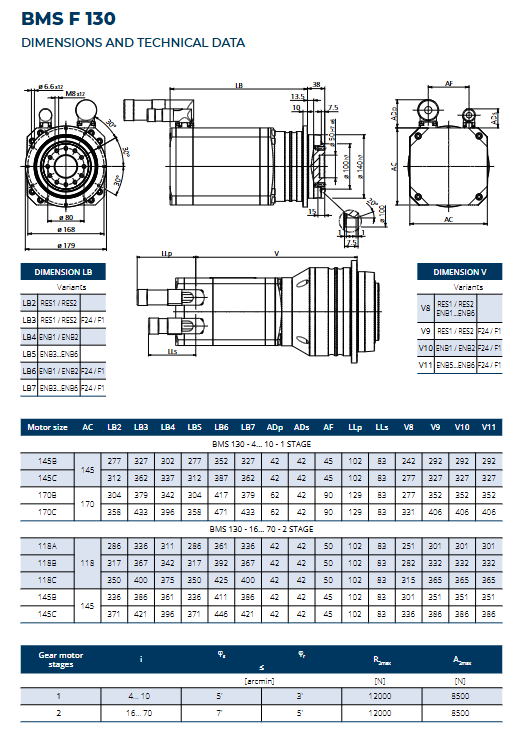
Each model (F060/F070/F090/F130/F160) provides 2D engineering drawings to distinguish different configurations and the total length of the machine:
LB: Length in the direction of the motor end (feedback/brake), distinguishing LB2~LB7, corresponding to different configurations such as rotary transformers, encoders, and brakes;
V: Length of the output side of the gearbox;
LLp/LLs: Cable joint installation dimensions;
Output flange, shaft size, and installation hole position. Provide a table of overall dimensions for different motor bodies (065A~170C) paired with various speed ratios of reducers.
Electrical Performance Data Sheet
Motor dataset: Key servo motor parameters such as rated speed, pole pairs, rated power, back electromotive force Ke, phase resistance Rpp, phase inductance Lpp, rated current In, and zero speed current I0 for each motor specification (065A-170C) at 230V/400V, B/M/H overspeed version.
The performance table of the deceleration motor (divided into three overspeed versions B/M/H) lists each model:
N ₙ₂: rated output speed; N ₐ₂: Maximum allowable acceleration speed;
M ₙ₂ rated torque; M ₀₂ locked rotor torque; M ₐ₂ maximum acceleration torque; M ₚ₂ Emergency stop peak torque;
In, I0, Ia, Ip various currents; Ct torsional stiffness; Rotor inertia J1; overall weight m; thermal derating coefficient Kp.
Output shaft bearing capacity: maximum radial force R ₂ max, maximum axial force A ₂ max.
Cable system
Power cable (orange, DESINA standard)
Metal bayonet circular connector, motor side 8-pin M23/M40; Drive side loose wire cold compression end;
Specification: 1.5/2.5/4/10mm ²; Optional with brake cable B or no brake NB;
Standard length: 3m, 5m, 10m, customizable; Bending resistant drag chain cable with shielding coverage rate greater than 80%;
Example of ordering code: MPC03-15-NB-C3.
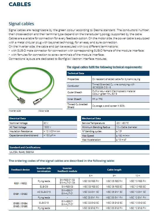
Feedback signal cable (green, DESINA standard)
Adapt to rotary transformers EnDat、Hiperface;
The driver end can choose SUB-D connectors or loose wires; Drag chain shielded cable;
Order code: MSC series.
Complete definition of pin allocation: power connector pins, RES rotary pins, EnDat, Hiperface signal pin definitions.
Selection table for matching BMS deceleration motor with Bonfiglioli ACU (ACTION) frequency converter
Divided into two types of operating conditions:
Non overload application: The zero speed current I0 of the motor is less than the rated In of the driver;
Overload application: Need to utilize the driver’s short-term overload capacity of 60 seconds; The table shows the ACU210/ACU410 driver models corresponding to different BMS motors (B/M/H versions, 230V/400V).