Bonfiglioli CM-PDP Profibus DP Communication Module
Module hardware disassembly
Power off, remove the upper and lower cover plates of the frequency converter, and access the Slot-B communication slot.
Install the matching PE grounding spring (M4 screw), insert the module into Slot-B, and the module comes with an M2 screw to lock onto the PE spring, achieving shielding grounding.
Knock open the prefabricated opening on the top cover for the DB9 X310 connector to pass through, and restore the cover plate.
Disassembly: Loosen the M2 screw, remove the buckles on both sides of the module, and alternately pull out the module.
Interface, bus terminal, cable
DB9-X310 pin (compliant with EN50170 Profibus standard)
Pin signal description
Shell shielding connected to PE
3 RxD/TxD-P B signal lines
8 RxD/TxD-N A signal line
5 DGND isolation areas
6 VP isolated 5V
4 CNTR-P repeater control signal
1,2,7,9 not used –
Terminal resistor S1 dialing: S1=ON at the first and last physical nodes of the bus; All in the middle are turned off.
Attention: The terminal resistance only takes effect when the module is powered on; It is prohibited to enable both onboard S1 and external active terminals simultaneously.
Cable: Profibus A-type shielded twisted pair must be used, with a large area of shielding layer connected to PE at both ends.
Auto Baud automatic recognition of baud rate, no need to manually set baud rate; The maximum bus length corresponding to different baud rates is 9.6k-1200m, 1.5M-200m, and 12M-100m.
Slave address, PPO object, master configuration
From the station address parameter 391 Profibus Node ID: range 0-126, factory 126; After modifying the parameters, the frequency converter will automatically reset and take effect; A DP bus can have up to 126 slave stations.
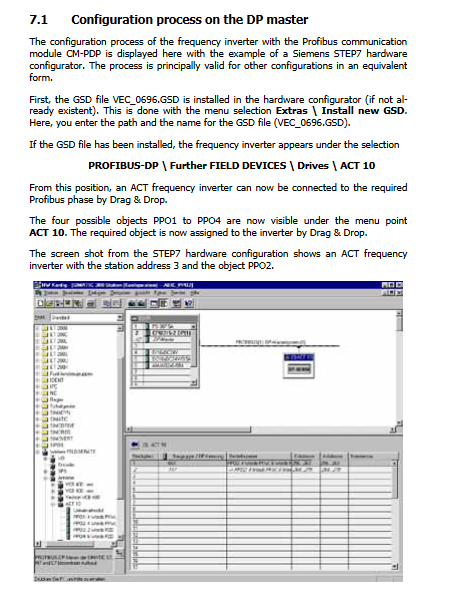
PPO Message Object (PROFIDRIVE): The frequency converter does not require local setting of PPO type, and is automatically recognized by the device through hardware configuration download from the DP master station.
PPO type total bytes PKW parameter channel PZD process data channel scan cycle
PPO1 12 ✅ 4-word PKW PZD1 (control word)+PZD2 (customizable actual value) 32ms
PPO2 20 ✅ 4-character PKW PZD1-PZD6 (fixed with 6 process characters) 32ms
PPO3 4 ❌ No PKW PZD1+PZD2 16ms
PPO4 12 ❌ No PKW PZD1-PZD6 32ms
PK-PKW channel: Read and write any frequency converter parameters (excluding string parameters);
PZD process data: Real time exchange of control words, given values, and actual values for each bus cycle;
PPO3/4 does not have a PKW channel and cannot read or write parameters. It only performs periodic control.
STEP7 main station configuration process: Import VEC_0699.GSD; Select PROFIBUS-DP \ Further Field Devices \ Drives \ ACT 10 from the hardware directory; Drag and drop the PPO object to assign to the slave and download the hardware configuration.
Supports DP standard SYNC/UNSYNC, FREEZE/UNFREEZE synchronous freeze commands for multi slave synchronous IO.
Message structure: PKW parameter channel+PZD process data channel
Byte order: Motorola big end format (high byte first, compatible with S7); Intel main station requires software high and low byte swapping.
5.1 PKW parameter channel (4 words, 8 bytes; equipped with PPO1/PPO2)
PKW=PKE (Parameter Identification)+IND (Index/Dataset)+PWE-H (Parameter High Word)+PWE-L (Parameter Low Word)
PKE: 4 bits high=AK (command/response ID), 12 bits low=PNU (frequency converter parameter number); SPM bit fixed=0, does not support spontaneous reporting.
IND index byte: The high byte is the dataset number 0-9, and the low byte is fixed at 0.
IND=0-4 → Write to EEPROM non-volatile storage; EEPROM has a lifespan of approximately 1 million cycles and prohibits high-frequency cyclic writing!
IND=5-9 → Write only to RAM, lost during power outage, suitable for PLC periodic data distribution | EEPROM dataset | RAM only dataset | | ————– | | 0 | 5 | | | 1 | 6 | | | 2 | 7 | | | 3 | 8 | | | 4 | 9|
AK command code (issued by the main station)
AK function
0 No command
Read 16 bit parameters
Write 2 16 bit parameters
Write 3 32-bit Long parameters
6 Read arrays (multiple datasets)
Write a 16 bit array with 7 characters
Write a 32-bit Long array with 8 characters
Reply AK from the station
AK meaning
0 No response
1 returns a 16 bit value
2. Return a 32-bit Long value
4. Return a 16 bit array
5. Return a 32-bit array
7 command execution failed; PWE-L carries fault codes
8 No PKW write permission
PKW handshake timing rules (key)
Idle state: The master station AK=0, and the slave station responds AK=0.
The main station writes non-zero AK commands.
Waiting for the slave station to respond AK ≠ 0, the master station will parse the response.
The master station writes AK back to 0 and waits for the slave station to respond that AK has changed back to 0. Only after this communication ends can the next command be issued.
PKW fault codes: illegal parameter number, parameter read-only, out of limit, dataset error, EEPROM read/write error, prohibited parameter write during operation, etc.
Numerical processing: Communication transmission with decimal point parameters to amplify integers; Such as transmitting 1030 at 10.3Hz.
5.2 PZD Process Data Channel
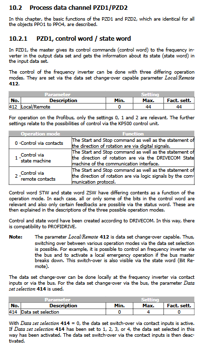
PZD1: Control word STW (master station → driver)/status word ZSW (driver → master station) parameter 412 Local/Remote Select 3 bus control modes:
Mode 0: Control via contacts: All start stop commands come from hardware DI, PZD1 control word is invalid; The status word still provides feedback on the driver’s status.
Mode 1: Control via state machine (DRIVECOM state machine, standard bus control): The bus control word implements the complete drive state machine; The external enable signal of hardware S1IND has the highest priority, and the bus cannot replace hardware enable.
Parameter 392 State transition5 defines the “enable run → ready” shutdown behavior: 0 free sliding; 1. DC braking (V/F only); 2 Slope shutdown (factory default).
Support Quick Stop, configurable for fast stop ramp, shutdown threshold, and hold time.
Mode 2: Control via remote contacts Virtual terminal: Control word per bit analog hardware digital input S1IND~S6IND; Hardware S1IND still needs to be enabled by hardware.
The status word ZSW includes: ready, closed, operation enabled, fault, quick stop, remote position, reaching the given position, limit activation, and two-level warning positions. After the fault occurs, there is a 15 second internal shielding time, and the fault confirmation reset must wait for this time.
PZD2~PZD6 Given and Actual Values
Standardization of Given Values (PROFIDRIVE Standard)
Reference standard: Parameter 375 Rated frequency rated frequency or 390 Profibus Reference (when 390 ≠ 0, this is used as the reference)
+100% = 0x4000 (16384); ‑100% = 0xC000; Range ± 200% (-32768~+32768).
Example: Reference 60Hz, output 30Hz=50% → Send 0x2000.
Parameter 434 Ramp setpoint Slope setting source: 1 is only internally given; 2 bus only given; 3 internal+bus overlay.
PPO1/PPO3 (only PZD2): Control word bit12-14 (IW1-IW3) dynamically selects what actual value PZD2 returns: actual frequency, effective value current, torque current, warning word, fault word.
PPO2/PPO4 (PZD1-PZD6 consists of 6 words): PZD2-PZD6 fixed return: actual frequency, total current, torque current, warning word, fault word; Bit12-14 is no longer effective.
Advanced features (firmware ≥ V4.0.5): The OUT PZD3~OUT PZD6 of PPO2/PPO4 can be used as a global source bus to issue PZD3-6, which can be directly used as a Boolean, 16 bit Word, and 32-bit Long signal source inside the inverter; Source code 750-761; Can be used for process controller settings, digital output control, dataset switching, torque/current settings, and can also be forwarded through the system bus EM-SYS.
5.3 Monitoring Parameters
281 DP Master OUT: Monitor the complete message sent by the PLC to the driver (VPlus read-only)
284 DP Master IN: Monitor the complete message uploaded by the driver to the PLC (VPlus read-only)
Only the VPlus software connected to the PC via KP232 adapter can read these two parameters; The Profibus interface cannot connect to VPlus.
Alarm and malfunction
Warning word parameter 270:16 bit encoding, including warnings for Ixt overload, radiator temperature, motor temperature, main power failure, V-band monitoring, etc.
Profibus DP related fault codes
F20-61: CM PDP module malfunction
F20-62: DP bus OFF, DP master station fault
F20-65: Profibus configuration error