



BENDER IRDH265 / IRDH365(ISOMETER ®) Insulation monitoring device
Product positioning and core functions
Applicable system: IT isolated power supply system; Can handle AC/DC hybrid systems with rectifiers and frequency converters; External couplers can be used to extend the voltage level of the tested system.
Core measurement principle: AMP adaptive measurement pulse superimposes positive and negative symmetrical pulse measurement voltage onto the system to calculate the system’s insulation resistance to ground; The measurement accuracy is not affected by the system’s ground leakage capacitance, and the response time will become longer as the leakage capacitance increases.
Main abilities
Dual level insulation alarm ALARM1, ALARM2, with adjustable resistance of 10-990 k Ω;
LCD displays insulation resistance values, which can distinguish between AC ground faults, DC L+ground faults, and DC L – ground fault locations;
Relay 2-channel conversion output, contacts normally open NO/normally closed NC software configurable;
Connection monitoring: detect PE/tested system wiring disconnection and poor contact;
Automatic self check: Version 3 and 4 models automatically self check every 24 hours when the insulation resistance is much higher than the threshold;
RS-485 serial interface outputs measurement data and alarm status;
M+/M – Analog output 0-400 μ A, external pointer insulation meter;
Password protection to prevent parameter tampering;
TEST/RESET composite button: short press reset, long press>2s machine function self-test; Support external TEST/RESET terminals.
Differences in hardware form
Model Installation Method Shell Weight
IRDH265 DIN rail/screw fixed rail yellow shell 825g
IRDH365 panel embedded 144 × 72 perforated panel black shell 1075 g
Important security rule: Only one activated ISOMETER insulation monitoring device is allowed to be connected to the same interconnected IT system; Before conducting the withstand voltage insulation test, the connection between this device and the tested system must be disconnected.
Terminal definition
Power supply
A1 (+), A2 (-): Auxiliary power supply Us; it is recommended to equip the front end with a 6A fuse.
Measurement circuit
L1, L2, L3/L (+), L (-): Connect to IT system three-phase/DC two poles;
KE: The protective grounding PE must be reliably grounded and cannot be disconnected;
AK: coupler interface, external AGH series high-voltage coupling device;
Signal terminal
M+/M —: Simulate 0-400 μ A output and connect an external insulation measurement meter;
<LT>: External reset/test, normally closed contact; Terminal short circuit fault memory latch takes effect, open circuit does not latch;
<PT>: Reserved;
A. B: RS-485 communication;
11-12-14: Alarm 1 relay conversion contact;
21-22-24: Alarm 2 relay conversion contact.
Panel human-machine components
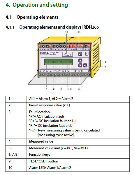
LCD screen: displays AL1 preset threshold, current insulation resistance, fault type (R AC fault/R+L+ground/R-L ground/Rs being measured)
ALARM1, ALARM2 yellow alarm LED;
TEST/RESET button;
Up, down, left, right navigation buttons;
Key Logic
Short press TEST/RESET (< 1 s): Reset alarm;
Long press TEST/RESET (>2 seconds): Start internal self-test; Self check shows’ TEST OK ‘as normal; The system displays TEST ALARM due to a ground fault.
Three layer menu system Setup 1/Setup 2/Setup 3
During parameter modification, insulation monitoring will temporarily pause; After 10 minutes of inactivity, the measurement interface will automatically return, and the parameters will be automatically saved to the EEPROM non-volatile memory.
Setup 1 [Basic Settings]
Password switch;
Set two-level alarm thresholds ALARM1 and ALARM2 (10~990k Ω);
Set two relay contact modes NO/NC;
Enter the Setup 2 expert menu switch.
Setup 2 [Extended Expert Settings]
Alarm fault type selection (ALARM1/ALARM2)
AC or DC: Alarm for both AC and DC faults;
Only AC: responds to communication faults only;
Only DC: responds to single pole DC grounding;
ONLY DC+/ONLY DC —: only responds to L+or L — single pole grounding;
SYST-TEST: Only system hardware fault alarm;
Choose AGH-AK80/AK160 as the coupler model;
Wiring connection monitoring switch;
Relay output flashing function (1Hz pulse output);
Check if the relay is activated during the self checking process;
Alarm delay switch, with a delay time of 1-10 seconds;
Set the maximum ground leakage capacitance CE MAX of the system (up to 500 μ F); The larger the leakage capacitance, the longer the measurement cycle;
Password setting, factory reset, and software version reading.
Setup 3 [Advanced Setting of Measurement Principles, Only Version 3-4]
Four measurement modes can be switched:
AMP (factory default): adaptive pulse measurement, universal for both AC and DC;
DC: Stacked with 27V DC measurement voltage, only suitable for pure AC systems;
UG/AMP: Rapid detection of asymmetric DC faults;
AMP/UG: AMP main measurement overlay asymmetric fast detection; DC fault quick response current can be set to 0.1~5mA.
External matching coupler AGH series (extended high voltage)
The upper limit of direct measurement for this machine body is AC 793V, DC 650V; Paired with couplers, it can expand high-voltage IT systems:
AGH204S-4: AC maximum 1650V with rectifier load system;
AGH520S: AC up to 7200V pure AC IT;
AGH150W-4: DC maximum 1760V DC IT.
The coupler is connected to the host through the AK terminal, and the corresponding AK80/AK160 parameters must be selected in the menu.
Communication interface RS-485
Electrical: Non isolated RS-485 (terminals A/B), maximum bus length of 1200mm;
Parameters: 9600 baud, 8 data bits, 1 start bit, 1 stop bit;
Output format: Continuously send ASCII data frames; Including measuring insulation resistance, ALARM1 threshold, ALARM2 threshold, relay status, and fault type; Can be connected to an upper computer or text display to read the insulation status.
Key technical parameters
Tested system
Direct connection host: AC 0-793V, DC 0-650V, frequency 50-400Hz;
Alarm setting range: 10 k Ω~990 k Ω; hysteresis of about 25%;
The maximum system leakage capacitance to ground is up to 500 μ F;
Multiple versions of auxiliary power supply units are available with AC/DC options; The overall power consumption is ≤ 6 VA;
Relay output: two conversion contacts; AC250V / DC300V; Mechanical lifespan of 12000 cycles;
Environment: working -10~+55 ℃, storage -40~+70 ℃, climate level 3K5;
Anti interference: Complies with IEC 61000, EMC Class A industrial grade; The impact and vibration meet the requirements of IEC 60068;
Certification: IEC 61557-8 UL Listed、CE;
Analog output M+/M —: 0-400 μ A corresponds to 0-100% range, without electrical isolation; To connect to a PLC, an isolation converter RK170 must be equipped.
Fault Information Description
ALARM E-KE: PE protection ground wire wiring abnormality;
ALARM L1-L3: All measurement wiring to the IT system is disconnected;
TEST ALARM: Ground fault detected during self check process;
If system faults are repeatedly reported: power off and restart; Still reproducing represents hardware damage to the device.
Wiring monitoring only alarms when all measurement leads are disconnected, and a single disconnection does not necessarily report a fault.
Ordering model and peripherals
The suffix meaning of the host version: -3/-4/-7/-8, corresponding to different insulation ranges and maximum leakage capacitance;
Peripheral: AGH high-voltage coupler; 72 × 72/96 × 96 external insulation indicator; RK170 isolated signal converter.
Important usage precautions
Before the voltage/insulation test, all connections between IRDH265/365 and the IT system must be disconnected, otherwise the device will be damaged;
The same IT isolated power grid only allows one ISOMETER host to be put into measurement, and multiple parallel connections may cause measurement abnormalities;
KE terminal PE ground wire is not allowed to be plugged or unplugged with power on;
AC/DC hybrid rectifier load: The rectifier must have a load current of>5-10 mA for DC side grounding faults to be detected correctly;
The larger the leakage capacitance of the system to the ground, the longer the measurement response time of the device, and the selection should confirm the on-site system CE parameters;
The M+/M – analog output is not isolated, and an isolation conversion module must be used when connecting to a PLC.
Typical application scenarios
Medical IT isolation power supply system;
Non grounded DC/AC/DC hybrid power grid for ships and rail transit;
Inverter, inverter intermediate DC circuit IT system;
Industrial isolation UPS, online monitoring of insulation status of ungrounded power supply.


