Delta Tau Turbo PMAC2 PCI Ultralite Programmable Multi Axis Motion Controller
Product Overview
Positioning: Full sized PCI bus expansion card, programmable multi axis motion controller. The board itself does not have a local axis interface and relies on the MACRO high-speed ring network to control up to 32 axes; It can also be connected to an external ACC-24P/ACC-24P2 expansion board, which can expand up to 32 external axis interface circuits.
Safety, Static Electricity, and Installation Standards
Static sensitive devices: The board contains static sensitive devices, and the operator can release static electricity by touching the grounded metal before contact; Prohibit contact with high insulation materials (chemical fibers, plastic films) and place them on conductive surfaces; Only qualified technicians are allowed to operate.
Industrial use requirements: It must be installed in the industrial control cabinet to avoid corrosive moisture, abnormal temperature, and conductive dust, otherwise the manufacturer does not guarantee the reliability of the equipment.
Safety regulations: Installation and maintenance personnel need to be familiar with electrical safety standards such as IEC and VDE; All components of the system are reliably grounded; Do not plug or unplug cables when they are live to prevent arcing; The operating status of the chassis cover must be closed; The components of the board are equipped with high voltage and high temperature.
Document Tag Definition
Warning: Danger of personal injury or death;
Caution: Risk of equipment damage;
Note: Important usage tips.
Model code and configurable selection
Model code format: 4-3-7-2-6-A-B-C-D-E-F-2-G-H-K-L-0-0, divided into multiple options:
A/B segment: CPU/memory/firmware: Provides multiple CPUs including 5C0/5C3 (80MHz), 5E0 (160MHz), 5E3 (200MHz), and 5F0/5F3 (240MHz); Paired with different SRAM and Flash memory capacities.
Segment C: PMAC firmware version, standard is 2-PMAC2.
D section: Clock crystal options: no options, 8A high-precision crystal oscillator, 16A battery backup parameter RAM, etc.
E section: MACRO interface options
Opt A: Fiber optic SC interface MACRO Ring;
Opt C: RJ45 electrical port MACRO Ring;
Combination options: Simultaneously fiber optic/electrical port+auxiliary RS-232.
F section: Communication options: 0, no options available; Add dual port RAM to Opt2B.
G segment: Axis/MACRO node options: Different IO and servo axis quantity configurations (8-axis/16 axis/32 axis).
H section: Analog acquisition option: 0 without ADC; Opt12 is an 8-channel 12 bit ADC; Opt12A is a 16 channel 12 bit ADC.
K-L: Factory reserved custom option space.
Specification parameters
1. Environmental specifications
Item | Parameter
Working temperature: 0 ℃~60 ℃
Storage temperature -12 ℃~82 ℃
Humidity 10% -95%, no condensation
2. Electrical specifications
Input power consumption:+5V about 2A; ± 12V about 100mA.
Onboard backup battery: 3.0V 1200mAh 2/3A lithium battery or 3.6V 1000mAh battery; The standard CPU configuration has a battery life of about 10 years; High speed CPUs will accelerate power consumption.
Connector Definition (Core Interface)
J1 (JANA) analog input (optional Opt12): 20 pin IDC socket, up to 16 single ended 12 bit ADCs; Two ranges: unipolar 0~+5V, bipolar -2.5V~+2.5V; Comes with a ± 12V reference output.
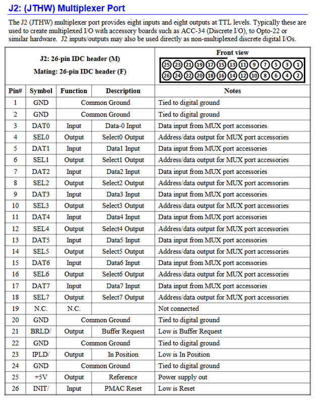
J2 (JTHW) multiplexing port, 26 pin IDC: 8 TTL inputs, 8 TTL outputs; Can be paired with IO expansion boards such as ACC-34 for multiplexed IO, or directly used as regular digital IO; with reset, position in place, and buffering request signals.
J3 (JI/O) universal digital IO, 40 pin IDC: 32 TTL5V bidirectional IO, configured input and output directions according to byte group software; Output phase clock and servo clock, providing+5V reference.
J5 RS-232 serial port (10 pin IDC): can be used as the main communication port and can communicate in parallel with PCI; Support sharing phase/servo clock among multiple PMAC boards; The default baud rate is 38400, which is configured by the variable I54.
J5A RS-422 auxiliary serial port (26 pin IDC): supports RS-232/RS-422, can synchronize multiple PMAC boards in daisy chain, and is used for MACRO ring network systems with more than 32 axes; Differential signal with clock synchronization signal.
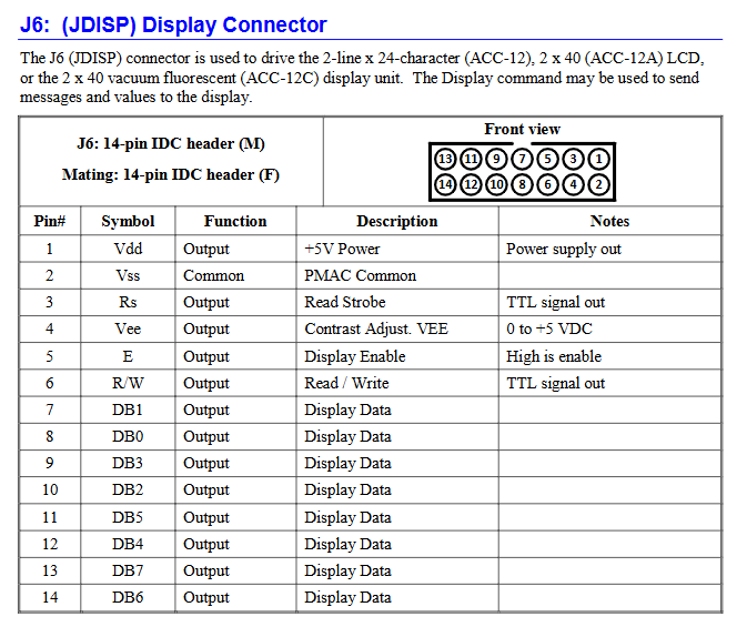
J6 (JDISP) display interface, 14 pin IDC: drives external LCD/VFD display module (ACC-12/ACC-12A/ACC-12C).
J7 (JHW) handwheel encoder interface 20 pin IDC: 2-channel orthogonal encoder input (handwheel/main reference encoder); Simultaneously provide 2 sets of pulse direction/PWM differential outputs.
TB1 logic power terminal block: TB1 is prohibited from being used when the board is inserted into the PCI slot and is powered by the PCI slot; When running independently offline, it is powered by TB1 and+5V is required; ± 12V is only used for ADC analog circuits.
TB2 watchdog relay terminal: provides normally open NO and normally closed NC contacts; Regularly close and conduct during normal operation; The watchdog is triggered/powered off frequently and is used for machine safety emergency stop.
MACRO ring network interface CN3, CN4
Option A (Fiber): SC multimode fiber interface, wavelength 1300nm, 62.5/125 fiber; IN receiving, OUT sending.
Option C (electrical port): RJ45 differential electrical signal MACRO ring.
E-Point jumper configuration on board
The document includes a silk screen layout diagram of the board, with all onboard jumper functions:
E0 reset lock: Short circuit forces the board to continuously reset; Default no jumper wires inserted.
E1 0 board (clock source) selection: default without jumper wires, this card is the main clock source Card0; Short circuiting serves as a slave card, with external input of phase and servo clock.
E2 40/60MHz operating frequency selection.
Re initialize control during E3 reset.
E4-E6: Reserved, reserved for future functionality.
E7 analog input reference source selection: Select internal reference or J1 external reference voltage.
E10A/B/C Flash storage selection, switch between different firmware storage partitions.
E15 MACRO electrical port internal loop test switch; By default, internal loopback is enabled (for testing purposes), and short circuiting to disable loopback is used for actual external MACRO ring network.
E16 MACRO input source selection: fiber optic input/RJ45 electrical port input, matched with E option A/C selection.
E17/E18 serial port source selection: Switch between using J5 (RS-232) or J5A (RS-422).
E19 watchdog disabled jumper, only short circuited during debugging and testing, must be removed for normal operation.
E20/E21/E22 power on/reset firmware loading source, only allows specified combinations, other factory specific.
E23 firmware reload enable: Short circuit allows serial/bus firmware reload, remove jumper wires for normal operation.