Foxboro DCS Compact 200 Series 16 Slot Horizontal Base RH916RB
Product Overview
RH916RB is a 16 slot horizontal mounting base that is only compatible with Compact200 series FBM fieldbus modules and is not compatible with standard 200 series FBM.
Installation method: Only supports horizontal DIN rail installation; The optional kit P0930AS can be installed on a 19 inch standard rack.
Support simplex and redundant Compact FBM modules; Passive backplane enhances system reliability.
Used for DCS system I/O subsystem, can be mixed with standard 200 series base for networking.
Main functional features
There are a total of 16 slots for Compact200 FBM modules;
Redundant 2Mbps Module Fieldbus (module fieldbus, HDLC serial bus);
Main and auxiliary 24V DC redundant power input;
On site I/O connectors, connected to on-site signal terminal components;
Redundant modules require the configuration of independent redundant adapters;
DIP dip switch is used to set the base ID;
Hot expansion capability: With redundant A/B bus conditions, the system can add Compact/standard 200 series bases to the existing base chain without shutting down;
Passive backplane design improves system reliability.
Module addressing Letterbug (6-character identification)
The FBM module on the Compact200 base does not have a physical letterbug tag, and the software address is generated by dialing the base ID and the physical location of the module.
Base DIP switch setting base number: 0&1 or 2&3;
The 16 slots are divided into 8 slots in the front and 8 slots in the back: the first 8 slots use the first base number, and the second 8 slots use the second base number;
The first 4 digits of the 6-character letterbug are shared among all modules on the same base chain; The 5th digit is taken from the base number, and the 6th digit is taken from the position numbers 1-8 inside the slot.
Detailed algorithm reference manual B0400FA “Standard and Compact 200 Series Subsystem User’s Guide”.
Base chain hybrid configuration rules
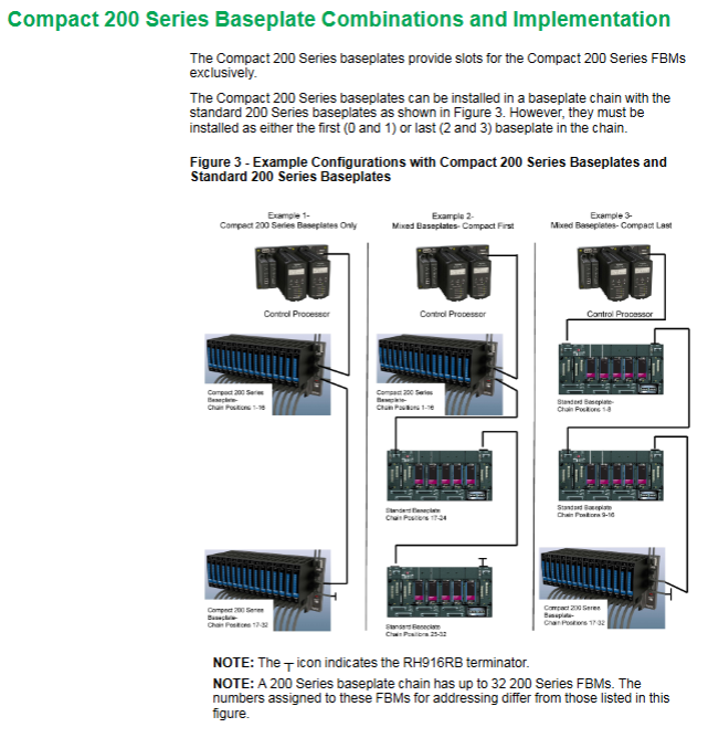
The Compact200 base can only be placed at the front end (0&1) or the back end (2&3) of the entire base chain, and cannot be placed in the middle of a standard 200 base;
The entire 200 series base chain can support up to 32 FBM modules;
Three networking modes: Compact200 base only; Compact at the beginning of the chain; Compact is at the end of the chain.
Hardware interface and interconnection
Interface Definition
A: FBM module connector;
B: Main power input;
C: Secondary power input;
D: Module bus input (from controller CP or previous base);
E: Module bus output (connected to the next base; the end of the chain must be connected to the terminator RH916RB);
F: On site I/O signal connector.
Module Fieldbus
FCM2F2: 2 km; FCM2F4: 4 km; FCM2F10: 10 km; the total distance of up to two stages of series FCM2F10 can reach 20km;
Redundant configuration paired with FCM2F; Non redundant, only using a single block.
Speed: 2Mbps HDLC, A/B redundancy;
Use shielded twisted pair cables; The cable between single base sections is 0.125-60 meters, and the total maximum length of the bus is 60 meters;
Fiber optic extension: Bus fiber optic extension is achieved through FCM2F2/FCM2F4/FCM2F10 fiber optic modules;
power input
Redundant 24V DC power supply, allowing+5%/-10%;
Compatible power supply models: FPS480-24, FPS400-24, FPS240-24, FPS120-24;
The allowable length of the power cable is 0.4~2.1mm.
On site circuit: When installed according to manual B0400FA, the on-site circuit belongs to Class 2 non ignition circuit.
Module layout rules
Non redundant FBM: can be placed in any available slot;
Redundant FBM modules must occupy adjacent odd even pairing slots and be equipped with redundant adapters;
The module supports hot plugging: disassembling and assembling FBM does not require disconnecting the on-site terminal cables, power supply cables, and communication cables.
Supporting terminal/splitter accessories
RH916RB bus terminator: used at the last base end of the bus chain to achieve bus terminal matching.
RH926KW (replacing P0926KW) terminal/splitter: capable of separating and outputting A/B bus signals; Used for building redundant cross base cabling, supporting non-stop addition of bases.
The Compact200 base does not support GPS time gating signals.
Non-stop expansion condition
To add a base to the running base chain, the system must be configured with A/B redundant buses, paired with RH926KW branch terminal, without interrupting bus communication.
Compliance certification
EMC electromagnetic compatibility: meets EU 2014/30/EU, EN61326:2013 A-class emission, industrial anti-interference level;
Security certification
UL/UL-C: Suitable for Class I Div.2 A-D group, T4 temperature group (installed in the cabinet);
ATEX:Ex nA IIC T4 Gc, Used for Zone 2 hazardous areas; Comply with the Low Voltage Directive 2014/35/EU and the Explosion Protection Directive 2014/34/EU;
RoHS: Compliant with EU RoHS 2011/65/EU and revised directives.
Environmental specifications
Relative humidity: 5-95%, no condensation;
Environmental corrosion level: ISA-S7.1.04 G3 severe level; Pollution level 2;
Altitude: working -300~+3000 m; transportation -300~+12000 m;
The cabinet will further improve the actual environmental conditions of the base, and it is necessary to refer to the PSS specification book corresponding to the cabinet.
Physical specifications
Install
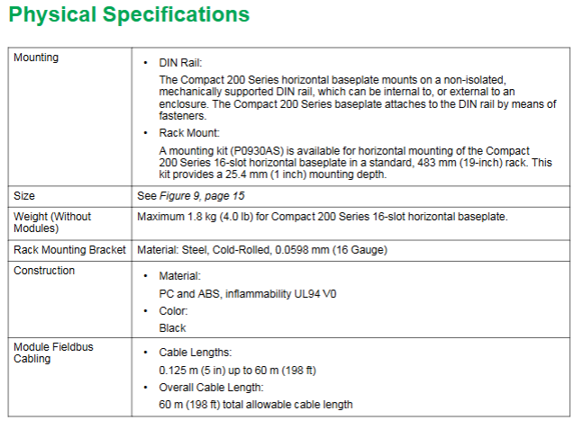
DIN rail: Non isolated DIN rail, can be used inside/outside the cabinet;
19 inch rack: optional kit P0930AS;
Dimensions: 443.6mm (length) × 214.4mm (height) × 39.8mm (thickness);
Weight: Maximum 1.8 kg (4.0 lb) without module;
Material: PC+ABS plastic, UL94-V0 flame retardant, black; The rack mounting bracket is made of 16GA cold-rolled steel.