ABB AO2040-CU Ex (2G Class) Central Unit Operating Instructions
Installation
1. unboxing and installation foundation
The equipment weighs about 28kg and requires two people to transport and install it; The installation base must have sufficient load-bearing capacity.
The supply includes: AO2040-CU Ex host, analyzer data sheet, AO2000 complete manual, this simplified manual, and compressed air pretreatment filter.
Applicable explosion-proof zones: Zone1, Zone2; Outdoor installation is strictly prohibited.
Provide overall dimensional drawings (in millimeters) for wall mounted installation structures.
2. Explosion suppression gas pipeline connection (positive pressure shell blowing gas)
Blowing medium: Compressed air, meeting ISO8573-1 Class3 standards; The working intake pressure is 250-500kPa (2.5-5bar).
The supporting compressed air filter must be installed as close as possible to the explosion suppression gas valve at the inlet (DIN ISO G1/4 interface) to filter impurities and prevent valve jamming and incomplete closure; Impurities generated during pipeline mechanical processing can damage valves, and in extreme cases, the display screen buttons may bulge outward.
Select pipelines with sufficient diameter according to the length of the pipeline to ensure the blowing flow rate; Reserve cable channel space during wiring.
3. General principles for electrical wiring safety
Internal isolation relays and controller wiring in the factory can be modified, but additional internal cables/components are prohibited. Changes must be recorded in the analyzer data sheet.
The equipotential/protective grounding should be connected to the on-site equipotential busbar first, with a minimum of 4mm ²; Grounding disconnection can pose a danger.
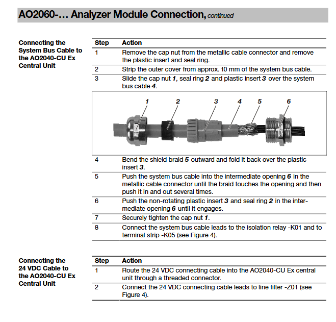
All cables must be reliably fixed; The metal shielding layer of the shielded cable (system bus) is connected to the metal cable joint.
Intrinsic safety signal cable: Only light blue M20 cable connectors can be connected, and the distance between the internal equipment and non intrinsic safety cables should be at least 8mm.
RS232/RS485/Ethernet in Zone 1 cannot be directly connected to the circuit board port and must use factory preset isolation relays.
The power cable can only be connected to the positive voltage cabinet control unit, and it is strictly prohibited to directly connect it to the shell wiring port, otherwise the explosion-proof function will fail.
Idle cable glands must be sealed with original plugs, with a tightening torque of 2.5Nm; M20 glands are compatible with cable outer diameters of 6-12mm.
4. Definition of Electrical Interfaces
Light blue M20: intrinsic safety signal; Black M20: Non intrinsic safety signal, 24VDC power supply for AO2060 module; Metal M20: AO2060 analyzer module system shielded bus.
Onboard components: Isolation relays K01~K04 (K01 standard, other options, maximum 30VDC/0.4A); K05 bus terminal block; Z01 24VDC line filter; B01 positive pressure shell control unit; Optional: ER144A/Ex condensation monitoring isolation amplifier, flow monitoring isolation amplifier, current output isolator, solenoid valve driver, switch isolation relay, etc.
AO2060 analysis module connection points: The system bus and 24VDC cable are key components of the explosion-proof system, and the cable cannot be shorter than 1 meter and must not be damaged; The bus shielding layer needs to be pressed outward with a metal gland; Connect 24VDC to Z01 filter terminal.
Condensation monitoring ER144A/Ex: The intrinsic safety signal line is routed through a blue gland and connected to E1/E2 terminals; The maximum total length of the lead is 75m; a 100k Ω resistor is connected in parallel to the sensor side nearby (the stainless steel probe version is already pre installed).
5. Status signal, grounding and power wiring
Protective grounding PE, minimum 4mm ² equipotential connection.
Passive relay terminals 21 and 22 for positive and negative pressure alarm: When the pressure inside the housing is less than 1.2hPa, the contact opens; Contact closure at pressure ≥ 1.2hPa; The maximum contact specification is 250V, 5A.
Power supply: Connect B01 control unit terminals L (17), N (15), PE; The power consumption is about 200VA; the power supply circuit must be equipped with a circuit breaker that can be easily disconnected and properly labeled; The equipment voltage cannot be adjusted on site.
Operation and Maintenance
1. Installation checklist before startup
Check the explosion-proof area and temperature group; Confirm non outdoor installation and secure installation; Smooth blowing of air; The shell is well sealed; Idle gland seal in place; The blowing pipeline is correct; Can complete pre blowing; All cable wiring is fixed correctly; Grid voltage matching nameplate; Control unit cover closed; Release of bypass mode; The blowing pilot pressure is qualified; The distance between intrinsically safe cables and other cables is ≥ 8mm.
2. Equipment startup steps
Connect the power supply; 2. Open the explosion suppression and purging gas source; After completing the pre purge, the solenoid valve switches to leakage compensation mode and the internal unit of the housing is powered on.
Attention: Purging the intake pressure above 5 bar will cause abnormal pre blowing.
Power on phenomenon: Power, Maint, and Error indicators light up simultaneously; The screen displays the firmware version for startup; After completion, enter measurement mode; The STOP MESSAGE software button appears on the screen to view temperature and flow alarms during the heating stage.
3. Bypass mode (maintenance specific)
Bypass activation will cancel the positive pressure explosion-proof protection and only allow confirmation of the absence of explosive gases on site or holding a hot work permit, which must be approved by the operation and maintenance manager before use. The bypass must be closed for normal operation.
Activation: Open the B01 control unit cover, press BYPASS, enter password 4711, and press MENU; The purge air is turned off, and the screen BYPASS flashes.
Close: Enter 4711 with the same key, MENU, Blow the air back up and cover the lid.
4. Regular inspections
Perform inspections on the installation checklist before reusing the startup.
Application, Structure, Principle of Positive Pressure System, Technical Specifications
1. Equipment purpose
Paired with the AO2060 series analysis modules (Caldos15/17, Magnos106, Uras14) to achieve gas measurement process control and monitoring; Wall mounted casing, following EN60079-2 positive pressure casing with leakage compensation. The equipment can introduce intrinsic safety and non intrinsic safety circuits, and non intrinsic safety circuits must pass through isolation relays; The circuit below the display keypad is an intrinsic safety circuit.
2. Working logic of positive pressure shell system
Start pre blowing: The blowing volume is indicated on the nameplate; The internal unit can only be powered on after the blowing is completed.
Normal operation: Maintain a slight positive pressure of about 2hPa inside the shell; The pressure control valve limits the pressure inside the casing. The air consumption for running the purge is about 40L/h.
Pressure protection interlock: If the pressure inside the shell is lower than 0.8hPa or higher than 15hPa, all internal equipment will lose power and the isolation relay circuit will be disconnected; After the pressure is restored, perform a complete pre blow and then power on again.
Status relay output: When the pressure is below 1.2hPa (blowing, bypass, fault), the contact is disconnected; The pressure is normally closed.
The internal volume of the shell is 36L; the minimum flow rate for pre blowing is 1L/s; Blow the intake pressure to 250-500kPa.
3. Main technical parameters
Project parameters
Explosion proof certification DMT 03 ATEX E 006; II 2G Ex px e d [ib] IIC T4
Working environment temperature+5~+50 ℃; Storage and transportation -25~+65 ℃
Power supply 115/230VAC non switchable, 48-62Hz, power consumption approximately 200VA
Shell protection IP54, weight approximately 28kg
Blow air ISO8573-1 Class 3; Maximum particle size 40 μ m, oil ≤ 1mg/m ³, pressure dew point+3 ℃
4. Electrical safety and EMC
Safety level I, compliant with EN61010-1; The low voltage side is protected by PELV for extra low voltage.
EMC meets EN61326-1 industrial grade and Class B interference limit.
5. Installation and maintenance specifications for electrical equipment in hazardous areas
Follow the EN60079-14 explosion-proof electrical installation standard; Pay attention to anti-static measures.
Non intrinsic safety circuit maintenance must be powered off, and the circuit breaker must be hung with a warning sign reading “Do not close”; Intrinsic safety circuits can be operated with electricity, but attention should be paid to the capacitance and inductance parameters of the testing equipment.
Periodic inspection: Explosion proof electrical equipment without continuous online monitoring shall be inspected by certified electricians at least every 3 years.
Maintenance can only use original spare parts from the factory; After the repair of components that affect explosion-proof performance is completed, they must be inspected and certified by experts; ABB’s on-site/return to factory maintenance can exempt third-party expert re inspection.