Installation Instructions for Elmo Gold Tuba (G-TUB Series) Servo Drive
Product Overview
Gold Tuba is a wall mounted high-power servo drive that can drive permanent magnet synchronous brushless motors, brushed DC motors, linear motors, and voice coil motors; Support vector control, sine/trapezoidal commutation; Support standalone independent operation or multi axis distributed real-time network systems.
Main power supply: can be directly connected to the mains (without the need for isolation transformers), supports single-phase/three-phase AC input;
Mandatory requirement for external 24VDC auxiliary power supply to maintain control circuit in case of main power failure;
Built in discharge chopper (Shun regulator) to process motor regeneration energy;
Model coding rules G-TUB XX/YYY E R S S O
XX: Continuous current; YYY: Rated AC voltage;
E/R: Feedback on hardware version; S: Standard/Extended I/O; O: Whether STO output is available or not;
Bus version:
E version: EtherCAT; F version: with onboard switch EtherCAT; S version: CANopen.
Main hardware specifications
Project parameters
Dimensions 241 × 86.1 × 180.1 mm
Weight 3.25 kg
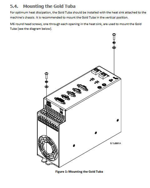
Installation method: Wall mounted, M6 screws, radiator attached to the chassis to ensure heat dissipation
Power models G-TUB30/230, 40/230, 30/480, 40/480
Continuous current of 30A/40A; Peak current 60A/80A
Maximum power output 9.5~25 kW; rated efficiency>98%
Auxiliary power supply 24VDC ± 10%; 30A model 20VA, 40A model 35VA
Built in peak discharge power of 5.9kW (230V model)/11kW (480V model)
environmental conditions
Working environment: 0-40 ℃; Storage -20~+85 ℃; Maximum non condensing humidity 95% RH;
The highest working altitude is 2000m; the anti vibration and shock resistance comply with IEC60068;
Security authentication
STO safety torque shutdown: SIL3, PL e, Cat.3 (EN ISO13849-1);
Compliant with the CE Low Voltage Directive UL61800‑5‑1、UL508C、CSA C22.2 No.14‑13。
Key points of the safety chapter
Only certified professionals are allowed to install, debug, and maintain; The equipment contains electrostatic sensitive components, and anti-static measures are required for operation.
It is strictly prohibited to plug and unplug connectors with power on; After a power outage, the capacitor is still charged. Wait at least 1 minute before touching the terminal. It is recommended to use a multimeter to confirm that there is no voltage.
The protective grounding PE must be reliably connected; It is strictly prohibited to connect the negative terminal VN of the DC bus to PE under direct connection to the mains topology, as it may cause permanent damage to the equipment.
Warranty: 12 months from shipment or installation, whichever comes first.
The STO safety function must be wired and verified to be functional, and the entire machine must comply with the Machinery Directive 2006/42/EC.
Overview of the overall machine interface
Front panel D-SUB connector
PORT-A (15 pin D-Sub): Encoder/Feedback 1; Supports incremental encoders, SSI/BiSS/EnDat absolute value encoders, and digital Hall Hall Hall encoders.
PORT-B (9-pin D-Sub): Encoder/Feedback 2; Incremental, analog interpolation encoder, and rotary transformer solver.
PORT-C (15 pin high-density D-Sub): analog encoder differential output, 1-channel differential ± 10V analog input.
I/O (15 pin high-density D-Sub): Standard digital I/O: 6 inputs, 4 outputs; Supports TTL/PLC source/drain type.
Network I/O (26 pin high-density D-Sub, expansion I/O option): 12DI+6DO, second differential analog input.
USB Mini-B: Local debugging, compatible with EAS (Elmo Application Studio) software.
Network port (choose one hardware version)
EtherCAT version: Dual RJ45 (IN/OUT), daisy chain networking; Some models come with onboard dip code address switches;
CAN version: Dual RJ45, CANopen bus.
Bottom Phoenix plug-in terminal (3.81mm spacing)
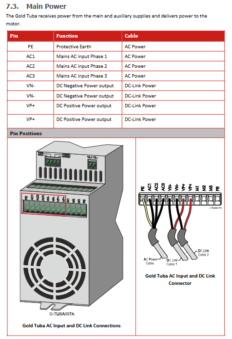
AC1/AC2/AC3: Main AC input; PE protected area;
VP+, VN —: DC bus output, supporting multi driver DC-LINK common bus, realizing multi axis regenerative energy sharing;
M1/M2/M3: Motor three-phase power output;
VL+/VL —: 24VDC auxiliary power supply;
STO1, STO2, STORET: Dual STO safety torque shutdown input.
The supporting Phoenix terminal model document is provided, please pay attention to pairing when purchasing.
Key wiring specifications
Priority should be given to using double-layer shielded twisted pair cables with drain wires for feedback and I/O cables; The D-Sub metal casing must be crimped onto the cable shielding layer;
Separate the routing of power cables (motor, AC main power) and signal feedback cables to reduce interference;
Encoder cable shielding: driver side crimping D-Sub metal casing; Motor side shielding connected to motor casing PE;
The direct connection to the mains power mode can be single-phase (only applicable to 230V models) or three-phase; Supports multi driver DC bus parallel connection and common DC bus topology, and one Tuba’s built-in discharge can serve the entire bus network.
Auxiliary 24V must use isolated power supply; It is prohibited to take 24V from non isolated power sources on the main power side.
Motor wiring
Brushless motor connected to M1-M2-M3 three-phase+PE;
Brushed DC motors use M2 and M3 phases; M1 is vacant;
Automatic identification of commutation phase sequence during EAS software debugging phase; When copying project files from multiple drives, the motor phase sequence must be consistent.
Feedback port division of labor
Port A: Incremental encoder, SSI/BiSS/EnDat absolute value encoder, digital Hall sensor;
Port B: Incremental encoder, analog SIN/COS encoder, rotary transformer solver (only R hardware version supports rotary transformer);
Port-C: Simulate encoder output (to provide position feedback to the upper controller), plus a differential analog input.
STO safety torque shutdown
Dual redundant STO input, supporting TTL level or PLC source level; Some models support STO status output (which may occupy some common I/O resources).
Digital I/O mode
I/O supports three electrical modes, determined by hardware model:
TTL mode (5V level)
PLC Source Type
PLC Sink leakage type standard I/O: 6DI/4DO; Extended NETWORK – I/O options: 12DI/6DO+second analog input.
Communication interface
USB 2.0 Mini-B: Local debugging and downloading parameters on the computer, EAS software;
EtherCAT: Slave device, IN-OUT daisy chain; Dual LED indicator links and status; F model with hardware dialing setting station number; Follow EtherCAT standard testing;
CANopen: RJ45 interface, CAN_H / CAN_L / CAN_RET; The terminal resistance at both ends of the bus must be 120 Ω, otherwise the bus will hang.
Cooling, fan, and status indicator lights
Smart Fan: When the radiator temperature is ≥ 60 ℃ or the discharge resistor overheats, the fan will start;
Drive status LED: red/green dual color; Flashing red during the startup phase; Fault red is constantly on; Ready green;
The EtherCAT status LED (ECAT status) indicates the running/fault status of the EtherCAT slave station.
The heat dissipation section provides a power loss chart, including rectifier bridge losses; Theoretical worst-case scenario, actual losses will be 10-20% lower.
Power on initialization process
Complete mechanical installation, complete all wiring, check PE grounding, STO wiring, 24V auxiliary power polarity, and AC main power;
Prioritize connecting the 24VDC auxiliary power supply before connecting the AC main power supply;
Connect to PC via USB and run EAS II software; Complete driver identification, motor identification, parameter configuration, and tuning;
Manual reminder: For complete parameters and command details, please refer to the “MAN-G-Panel Mounted Drives Hardware”. This installation manual does not describe the motion control function.