Kongsberg Maritime AS Distributed Processing Units Engine Safety Unit (ESU)
The Engine Safety Unit (ESU) product description released by Kongsberg Maritime AS states that its core function is engine safety monitoring and emergency shutdown, with multiple built-in redundancies and extensive internal self checking functions. Key configurations include dual redundant 24VDC power input, dual CAN bus communication interface, multi-channel digital input/output, and solenoid driver. The technical parameters include a power supply voltage of 18-32VDC, a working temperature of -15 ℃ to+70 ℃, a protection level of IP20, and a weight of 1.7kg. It has been certified by multiple classification societies such as DNV and CCS and is suitable for safety monitoring scenarios of engines, compressors, and other equipment.
Core functions and features
Core purpose
Engine sensor monitoring
RPM monitoring
Manual emergency stop
All parameters and circuit definitions are pre-set as engine supplier specifications
Key Features
Multiple built-in redundancy
Most lines have extensive internal self check features
Alarm and monitoring for all channels
Alarm and event timestamps (with an accuracy of 0.001 seconds)
Power overload detection
CAN bus status detection and error handling
Module temperature self-test (BIST)
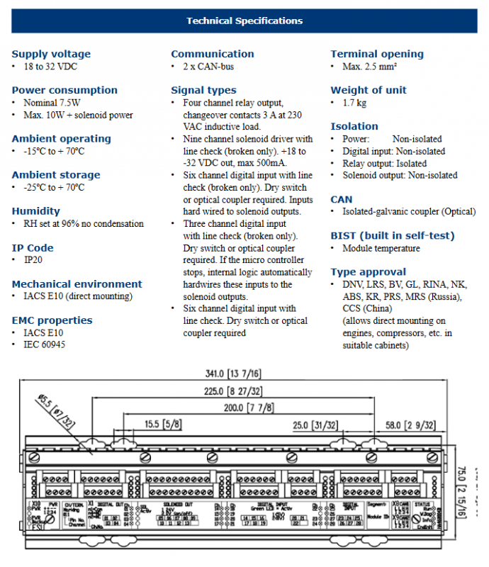
Technical specifications and parameters
Category specific parameters
Supply voltage 18 to 32 VDC (dual redundant power input with automatic switching function)
Power consumption nominal: 7.5W; maximum: 10W+solenoid power
Operating temperature: -15 º C to+70 º C; Storage: -25 º C to+70 º C
Humidity RH 96%, no condensation
Protection level IP20
The mechanical environment complies with IACS E10 (supports direct installation)
EMC characteristics comply with IACS E10 and IEC 60945
Communication interface 2 x CAN bus (with optoelectronic isolation coupler)
Terminal specifications support a maximum of 2.5 mm ² wire
Unit weight 1.7 kg
Isolation characteristic power supply: non isolated; Digital input: non isolated; Relay output: isolation; Solenoid output: non isolated; CAN: Optical Isolation
Classification Society Certification DNV, LRS, BV, GL, RINA, NK, ABS, KR, PRS, MRS (Russia), CCS (China)
Signal type and channel configuration
output channel
4-channel relay output (conversion contact): 3A @ 230VAC (inductive load)
9-way solenoid driver (with line break detection): output 18-32VDC, maximum 500mA
input channel
9-way digital input (for shutdown, with line detection): requires dry contacts or optocouplers, hard connected to solenoid output
6-way digital input (with line break detection): requires dry contacts or optocouplers
3-channel digital input (with line break detection): requires dry contacts or optocouplers; If the microcontroller stops working, the internal logic will automatically hard connect these inputs to the solenoid output
6-way digital input (with line detection): requires dry contacts or optocouplers
Channel linkage design
Digital input channels 14-19 are directly connected to output channels 5-13
If the module CPU fails, digital input channels 20-22 are directly connected to output channels 5-13