DEIF Multi line 2/version 2-GS Multi functional Generator Protection and Control Unit
Product basic information
A multifunctional generator protection and control unit based on microprocessors provides an integrated solution for medium and large generator units, supporting three application scenarios: independent operation, parallel connection of multiple units, and parallel connection with the power grid. Its core value is to integrate protection and control functions, reduce deployment costs, and improve operational reliability.
Differences in core functions and models
The three models of the Multi line 2 series each have their own focus on functions, with standard and optional functions covering the entire scenario of power generation control, as follows:
Model Core Positioning Standard Features Optional Features
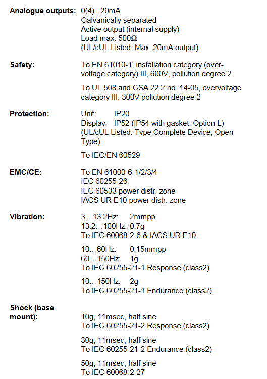
GPU generator protection unit with 3-phase measurement, overcurrent/reverse power protection, alarm output, kWh/kVArh counting synchronization control, load dependent start stop, engine communication, analog output
GPC generator parallel controller synchronization, load distribution (active/reactive), power/frequency control, parallel operating voltage/VAr/PF control, multiple communication protocols, I/O expansion, engine interface
PPU universal control unit basic protection and control, fixed frequency/power mode, alarm display similar to GPC, focusing on universal scenario adaptation
Core standard functions:
Control functions: synchronization, active/reactive load sharing, power/frequency regulation;
Protection functions (ANSI standard): reverse power (32), level 1/2 overcurrent (51), frequency mutation (ROCOF), vector jump, etc;
Display and alarm: LCD screen displays data/status text, GSM SMS alarm, remote alarm suppression/confirmation;
Measurement system: 3-phase true RMS measurement, voltage/current input is galvanic isolated.
Optional feature extensions: voltage/VAr/PF control, power management, serial communication (CANopen/Modbus/Profibus, etc.), additional operator display screens, engine specific interfaces (Caterpillar/MTU/Cummins), I/O expansion cards, etc.
Installation and hardware configuration
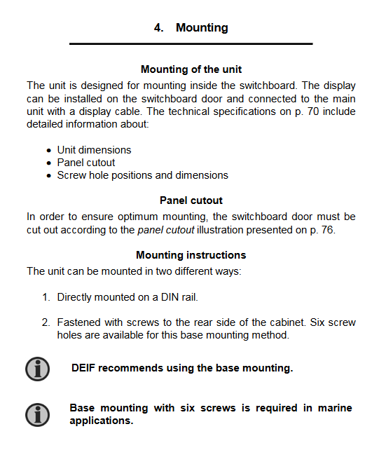
Installation method: Supports two installation modes to meet different scenario requirements:
DIN rail installation: universal scenarios;
Installation of 6-screw base: Recommended by DEIF, mandatory in marine scenarios to ensure stability in vibration environments.
Panel openings and dimensions:
Panel opening size: 10mm × 30mm (H × W);
Display screen size: 115mm × 220mm (H × W);
Main unit weight: 1.6kg, optional accessories (J1/J3: 0.2kg, J2: 0.4kg).
Hardware core structure:
The top of the unit contains 8 functional slots (Slot 1-8), corresponding to power board, measurement board, I/O board, communication board, engine control card, etc;
Terminal block: AC measurement terminal supports 1/5A current input and 100-690V voltage input, relay output terminal supports 250V AC/24V DC, 5A load (unit status output 1A);
Display screen: It can be independently installed on the switch cabinet door and connected to the main unit through a dedicated cable, with a maximum cable length of 6m.
Wiring specifications and requirements
Wiring is the core process of installation, and the document provides detailed requirements for AC connection, DC connection, relay output, communication wiring, etc. The key points are as follows:
AC connection:
Supports three types of wiring configurations: three-phase, single-phase, and phase separation, which need to be selected according to the type of distribution system;
Neutral line (N): Only three-phase+neutral line systems need to connect terminals 84 (generator neutral) and 88 (bus neutral), and systems without neutral lines are left vacant;
Grounding of current transformer: S1 or S2 terminals can be selected for grounding, and the cable needs to be protected with a 2A slow melting fuse;
Circuit breaker wiring: If the “synchronous power-off” function is enabled, it is recommended to use an automatic fuse with auxiliary contacts to avoid damage to the fuse and accidental closing.
DC connection and relay output:
Load sharing line: 37 (active) and 39 (reactive) terminals, signal range ± 0~5V DC, must use shielded twisted pair cables;
Binary input: 12/24V DC bidirectional optocoupler, impedance about 4.7k Ω, ON state voltage 8-36V DC, OFF state<2V DC;
Relay output: It is necessary to install noise suppression components to avoid interference caused by inductive loads that may result in unit reset errors.
Communication wiring:
Supported protocols: CANopen (H1), Modbus RTU (H2), Profibus (H3), J1939 (H5), etc., engine communication support Caterpillar CCM(H4)、MTU MDEC(H5)、Cummins ECM(H6);
Cable requirements: Unified use of shielded twisted pair (such as Belden 3105A), 22 AWG (0.6mm ²), shielding coverage rate ≥ 95%;
Terminal resistors: CANopen and J1939 protocols require the installation of 120 Ω terminal resistors at both ends of the bus, and Modbus/Profibus also needs to be configured for long-distance communication.
Core technical parameters
The technical parameters of the Multi line 2 series are unified, and the key indicators are shown in the table below, all of which comply with relevant IEC/EN standards:
Specific values/requirements for category key parameters
Measurement accuracy: Voltage/current measurement class 1.0 (IEC/EN 60688)
Negative sequence current measurement level 2.0
Measurement range voltage (phase to phase) 100-690V AC (± 20%), UL/cUL certified as 110-480V AC
Current 1/5A AC (from current transformer)
Frequency 30-70Hz
Power specifications: Auxiliary power supply 12/24V DC, continuous working range 8-36V DC, short-term 6V (1 second)
Maximum power consumption of 8W, requiring 2A slow melting fuse protection
Environmental adaptability working temperature -25 ℃~70 ℃, UL/cUL certified environment maximum 55 ℃
Storage temperature -40 ℃~70 ℃
Humidity 97% RH (no condensation, IEC 60068-2-30)
Vibration/shock vibration: 3-13.2Hz (2mmpp), 13.2-100Hz (0.7g); Impact: 10g (11ms, half sine)
Protection level: Main unit IP20 (IEC 60529)
Display screen IP52, optional IP54 with gasket
Response time: Bus overvoltage/undervoltage<50ms
Bus over/under frequency<50ms
Generator overvoltage/undervoltage 70-300ms
Fast overcurrent<42ms
Frequency mutation (ROCOF) 100ms (4 cycles)
Authentication and adaptation scenarios
Core certifications: UL/cUL Listed (compliant with UL508 standards), major classification society certifications (such as DNV, LR, etc.), GOST-R (Russia), T Ü V Nord (Germany), meeting compliance requirements in multiple regions worldwide.
Device adaptation:
Governor: compatible with mainstream brands such as GAC, Barber Colman, Woodward, Cummins, etc;
Engine: Adapt to communication with Caterpillar, MTU, Cummins and other brand engines through dedicated interfaces (H4/H5/H6 options);
Application scenarios: Medium to large generator sets, supporting independent operation, parallel operation of multiple units, and parallel operation with the power grid, suitable for scenarios such as ships and industrial power stations.