DEIF AGC 100 series generator set controller
The AGC 100 series generator set controller (firmware 4.0x. x) from DEIF in Denmark is a control device that supports multi scenario deployment, including sub models such as AGC 112/113/145/146. It adopts panel embedded installation (standard protection IP52, optional Option L can reach IP65), panel opening size 151 × 211+1mm (H × W), equipped with rich terminal interfaces, supports three-phase/single-phase/phase separation voltage and current wiring, compatible with Modbus RTU (RS485), CAN J1939 communication protocol, power supply range 6-36V DC (UL certified 7.5-32.7V DC), can adapt to generator set startup control, parameter monitoring, circuit breaker management, and supports external AOP-2 operator panel and external I/O module. Installation requires Performed by professionals, the factory default settings need to be adapted to the generator set before activation.
Installation specifications and hardware parameters
Installation method and protection
Installation type: panel embedded installation, standard with 8 fixed clips, protection level IP52;
Upgraded protection: Optional Option L (12 fixed clips+dedicated gaskets), with protection level increased to IP65;
Panel opening size: 151.00 × 211.00+1.00mm (H × W), converted to inches of 5.94 × 8.31+0.04 inches. It is necessary to strictly follow the size of the opening to ensure installation accuracy.
Tightening torque requirements
The tightening torque varies in different parts, and appropriate tools should be used to avoid damaging the equipment due to over tightening:
Remarks on torque values of fastening parts
Panel installation 0.15-0.20Nm (1.4-1.8lb in) embedded installation fixed
Terminal connection 0.5Nm (4.4lb in) for all wiring terminals
AOP-2 panel installation 0.7Nm (6.2lb in) additional operator panel
AOP-2 Sub-D screw 0.2Nm (1.8lb in) communication interface fixing
DC-DC converter terminal 0.5Nm (4.4lb in) expansion power terminal
Terminal definition and core functions
The AGC 100 series has a wide range of terminals, covering full functions such as power supply, input, output, and communication. The core terminals are defined in the following table (key terminals):
Terminal number type, technical parameters, core functions
1-2 power supply 6-36V DC (UL: 7.5-32.7V DC) equipment main power input, 1 is+, 2 is GND
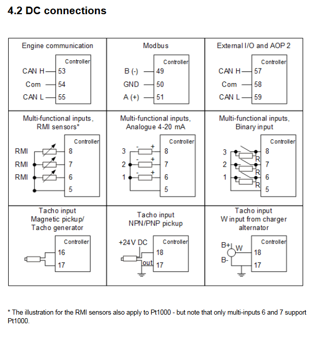
6-8 Multipurpose Input Supports 4-20mA, Pt1000, Digital Input Flexibly Adapts to Multiple Sensor Signals, Only 6-7 Supports Pt1000
10-15 digital input 12/24V DC bidirectional optocoupler receives digital signals such as remote start and start enable
16-18 speed input magnetic electric speed sensor, PNP/NPN, W terminal to monitor generator speed, 16 for MPU, 18 for W/L
19-20 emergency stop common terminal+input emergency stop control, 20 is the common terminal
21-27 relay output 21-23 (2A 30V DC/AC), 24-27 (8A 30V DC/AC) universal control output, configurable for startup preparation, alarm, etc
28-32 mains voltage inputs L1-L3, N monitor mains voltage/frequency, 31 terminals are not allowed to be connected without use
33-38 Generator Voltage Input L1-L3, N Monitor Generator Voltage/Frequency, 35/37 Terminals Not Used Prohibited Connection
39-44 generator current input L1-L3 s1/s2 monitoring generator three-phase current
45-48 circuit breaker relay 45-46 (generator circuit breaker, NO), 47-48 (mains circuit breaker, NC, Option M19 is NO) controls the opening and closing of the circuit breaker, 2A 30V DC/250V AC
49-51 Modbus RS485 49 (B -), 50 (GND), 51 (A+) support Modbus RTU/ASCII communication
53-55 CAN bus A 53 (CAN-H), 54 (Com), 55 (CAN-L) CAN J1939 engine communication
57-59 CAN bus B 57 (CAN-H), 58 (Com), 59 (CAN-L) connect to AOP-2 panel or external I/O module
Wiring specifications and scene adaptation
Core wiring requirements
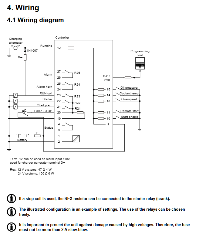
DC connection: The equipment power circuit needs to be connected in series with a 2A slow melting fuse to prevent high voltage damage to the equipment;
Digital input: All digital inputs are bidirectional optocoupler type, only mode switching and testing inputs support pulse signals, and the rest are fixed signals;
Circuit breaker configuration: Supports three types of circuit breakers: pulse type, continuous type, and compact type. The output terminals need to be configured through PC utility software;
Charger generator connection: Two feedback methods are available – D+terminal connected to terminal 12, or W terminal connected to speed input terminal. The 12V system is equipped with a 47 Ω 4W excitation resistor, and the 24V system is equipped with a 100 Ω 6W resistor.
Typical wiring scenarios
The device supports multi scenario wiring, with the following core scenarios:
Scene sub model, wiring type, core usage
Independent power supply for AGC 112 three-phase/single-phase/phase separated generator set operating on an isolated island, without mains connection
AMF (mains power failure switching) AGC 113 automatically starts the generator set for power supply in case of three-phase/single-phase/phase separated mains power failure
Power management AGC 145/146 three-phase with mains circuit breaker (145) or mains+contact circuit breaker (146) management
Communication Configuration Specification
Communication Protocol and Interface
Modbus RTU/ASCII: supports communication with PLC and other devices through RS485 interface (terminals 49-51);
CAN bus: The CAN J1939 protocol (terminals 53-55) is used for engine communication, and terminals 57-59 are used to connect to the AOP-2 operator panel or external I/O module (Option H8).
Requirements for communication cables
Cable type: Belden 3106A or equivalent shielded twisted pair, 22AWG (0.324mm ²), shielding coverage rate ≥ 95%;
Communication distance: maximum 300m. When the bus length exceeds 30m, a 120 Ω terminal resistor needs to be installed;
Shielding treatment: Ensure effective grounding of the shielding layer to reduce electromagnetic interference.
Extended Configuration
External I/O module: needs to be used in conjunction with AOP-2 panel, with a total terminal resistance of 120 Ω;
AOP-2 operator panel: equipped with DC-DC converter and 2 1m cables (one end RJ12, one end stripped), with a maximum communication distance of 300m.