Omron C200HX/HG/HE PLC Installation and Configuration Guide
In the field of industrial automation control, the importance of Programmable Controller (PC or PLC) as the “brain” of the system is self-evident. The C200HX, C200HG, and C200HE series PLCs launched by Omron are widely used in various control systems due to their flexible configuration, powerful processing capabilities, and high reliability. Based on the latest installation guide materials, this article will provide a detailed professional analysis of the system architecture, hardware installation, wiring specifications, and maintenance troubleshooting of this series of PLCs, aiming to provide engineers with a detailed practical reference.
Fundamentals of Control Systems and Working Principles of PLC
It is crucial to understand the infrastructure of the control system before delving into hardware details. A typical control system not only includes the PLC itself, but also covers the complete hierarchy from the upper computer (such as process control computer, factory computer) to the lower actuators (such as sensors, motors, solenoid valves). PLC plays a core role in this hierarchy, receiving on-site signals through input devices, performing logical operations based on user programs stored in memory, and controlling mechanical actions through output devices.
1. Working cycle of PLC
The operation of PLC is not arbitrary, but follows strict scanning cycles. A complete PC cycle consists of four main stages:
Overseeing: self diagnostic processes such as watchdog timer operations, program memory testing, etc.
Data input/output: Read the input signal and refresh the output signal.
Instruction execution: Execute user program logic.
Peripheral services: handle interactions with programming devices, communication boards, etc.
The total time of this cycle is called the ‘cycle time’. For the C200HX series, its basic instruction processing speed can reach 0.1 microseconds, greatly improving the system’s real-time response capability. Understanding this mechanism is crucial for designing complex control logic, as the length of the cycle time directly determines the system’s response speed to input signals.
System configuration and hardware architecture
The C200HX/HG/HE series PLC adopts modular design, allowing users to flexibly configure the system according to their actual needs. Its basic structure includes a CPU rack, an expansion I/O rack, and various functional units.
1. CPU rack
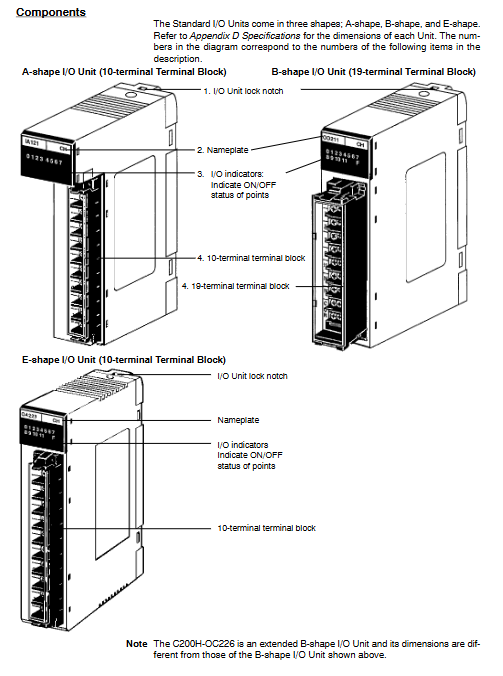
The CPU rack is the core of the control system, consisting of a CPU motherboard, CPU unit, power unit, and I/O unit.
CPU Unit: C200HX/HG/HE offers multiple models, ranging from entry-level C200HE-CPU11-E/ZE to high-performance C200HX-CPU85-ZE. Different models have differences in program capacity, I/O points, Extended Data Memory (EM), and instruction execution speed. For example, C200HX-CPU85-ZE has up to 63.2K words of user program memory and 16 banks of extended data memory, making it suitable for handling extremely complex control algorithms. The front of the CPU unit integrates indicator lights (RUN, ERR, INH, COMM), memory box slots, DIP switches, as well as peripheral ports and RS-232C ports.
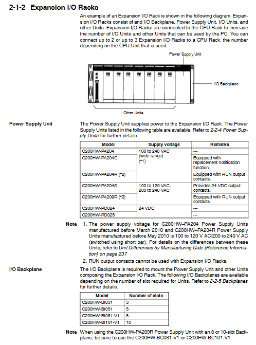
Power supply unit: The power supply unit is installed in the first slot of the base plate and is responsible for supplying power to the system. The models include AC input (such as C200HW-PA204, supporting 100-240VAC wide voltage input) and DC input (such as C200HW-PD024, supporting 24VDC). Some high-end models, such as C200HW-PA209R, offer higher output current (9A) and RUN output contacts, while C200HW-PA204C has a unique “replacement notification function”. When the power supply life is about to end, it will alert the user to replace it through an alarm output to avoid accidental shutdown.
Base board: divided into CPU base board and I/O base board, providing various specifications such as 3 slots, 5 slots, 8 slots, and 10 slots. The connectors on the motherboard are responsible for connecting various units and connecting the expansion rack through I/O connection cables.
2. Expand the I/O rack
In order to meet the demand for a large number of I/O points, the system allows the connection of up to 2 to 3 expansion I/O racks (the specific number depends on the CPU model). The expansion rack is connected to the CPU rack through I/O connection cables (with a total length not exceeding 12 meters), increasing the physical coverage and control scale of the system.
3. Special functional units and networks
In addition to standard I/O units, this series of PLCs supports a wide range of special I/O units, such as analog input/output units, temperature control units, high-speed counting units, position control units, etc. In terms of network communication, it supports multiple network architectures such as SYSMAC LINK, SYSMAC NET, Host Link, DeviceNet, etc., making it easy to build hierarchical distributed control systems.
Installation environment and physical deployment
Correct installation is a prerequisite for ensuring the long-term stable operation of PLC. There are strict regulations in the installation guide that must be followed.
1. Environmental requirements
The working environment of PLC is directly related to its lifespan. Installation must be avoided in the following environments:
Direct sunlight, temperature or humidity exceeding specification range (operating temperature: 0 to 55 ° C, humidity: 10% to 90% without condensation).
There are corrosive, flammable gases or large amounts of dust (especially iron powder), salts present.
Strong electromagnetic interference or vibration source.
The design of control cabinets is crucial to cope with harsh environments. It is necessary to maintain ventilation inside the cabinet, install cooling fans if necessary, and ensure that the cabinet meets NEMA standards to prevent dust and water.
2. Installation details
Installation direction: The PLC must be installed vertically to ensure a good heat dissipation duct. Do not install horizontally or upside down.
Spacing: In order to facilitate wiring and heat dissipation, at least 20mm of space should be reserved above and below the rack; It is recommended to maintain a spacing of 70mm to 120mm between racks.
DIN rail installation: Supports standard DIN rail installation, but in environments with high vibration, it is recommended to use screws to directly fix to the base plate to improve shock resistance.
Anti static: Before touching the unit, be sure to contact a grounded metal object to release static electricity and prevent electrostatic discharge from damaging sensitive semiconductor components.
Wiring specifications and anti-interference measures
The quality of wiring directly determines the accuracy of signal transmission. Incorrect wiring can not only cause equipment damage, but also potentially lead to safety accidents.
1. Power wiring
AC power unit: When wiring, attention should be paid to selecting the voltage terminal (for early models), while modern wide voltage models (such as PA204) do not require manual switching. Be sure to use crimping terminals and do not directly connect bare wires. The ground (GR) terminal must be connected to a grounding electrode below 100 Ω to protect equipment and personnel safety. The LG terminal is a noise filtering neutral terminal, usually short circuited to the GR when interference is severe.
DC power unit: When wiring, it is necessary to distinguish between positive and negative poles. To comply with the EC directive, DC power supplies should have reinforced insulation or double insulation.
2. I/O wiring
Terminal tightening: The torque of the wiring screw should be controlled at 0.8 N · m. Too loose can lead to poor contact, while too tight may damage the terminals.
Label management: During the wiring process, keep the protective label at the top of the unit to prevent wire shavings from falling into the interior of the unit; After wiring is completed, be sure to remove the label to avoid affecting heat dissipation.
Cable isolation: I/O signal lines and power lines should be routed separately as much as possible. If parallel laying is necessary, the spacing should be kept at least 300mm. For AC input/output lines, it is recommended to use shielded cables and ground the shielding layer.
3. Noise countermeasures
The industrial site is filled with electromagnetic noise. For inductive loads such as relays and solenoid valves, surge suppressors (such as RC circuits, diodes, or varistors) must be connected in parallel at both ends of the load to absorb the reverse electromotive force generated at the moment of disconnection and prevent damage to the PLC output contacts. For the relay output of high-frequency switches, attention should be paid to their electrical life limit (about 300000 cycles), and intermediate relays should be used for isolation if necessary.
Programming equipment and system debugging
After the system is built, it needs to be debugged through programming equipment. C200HX/HG/HE supports two main programming methods:
Programming console: such as C200H-PRO27-E, connected to the peripheral port of the CPU, suitable for simple program modification and monitoring on site.
CX Programmer software: runs on IBM PC/AT compatible machines, connected through RS-232C ports or dedicated cables (such as CQM1-CIF02), providing a graphical programming interface and powerful debugging capabilities.
When powering on for the first time, check if the programming controller’s display is normal and enter the correct password (Clear+Monitor key). Before downloading the program, make sure the CPU is in Program mode to avoid unexpected conflicts with running programs.
Maintenance, troubleshooting, and component replacement
Although PLC is sturdy and durable, regular inspection and maintenance are essential. The manual provides a detailed process for maintenance and troubleshooting.
1. Troubleshooting
PLC has powerful self diagnostic function. Users should first observe the status of the indicator lights on the CPU panel:
RUN light not on: Check if the program is missing the END command or if there is a serious hardware error.
ERR light flashing: indicates a non fatal error (such as low battery voltage), the system can continue to operate, but it needs to be dealt with in a timely manner.
ERR light constantly on: indicates a fatal error, the CPU has stopped running, and a user program or hardware malfunction needs to be checked.
INH light on: indicates that the output disable bit (SR 25215) is set and all outputs are forcibly cut off.
2. Component replacement
Fuse replacement: Some output units (such as OD411, OA221) are equipped with fuses. If the fuse indicator light is on, it indicates that there is a short circuit on the load side. Before replacement, the power must be cut off and UL/CSA certified fuses recommended by the manufacturer must be used.
Relay replacement: For relay output units (such as OC221), relays are vulnerable parts. If adhesion or poor contact is found, the unit housing should be opened after power failure, and a new relay (model G6B-1174P-FD-US-M) should be replaced with the accompanying relay extractor.
Battery replacement: The battery (C200H-BAT09) is used to maintain data in RAM during power outages. When the ERR light flashes and the programmer displays “BATT FAIL”, the battery must be replaced within one week. The replacement process should be completed within 5 minutes of power on or power-off to prevent data loss. The normal service life is about 5 years (25 ° C).
3. Regular inspections
It is recommended to conduct regular inspections every 6 months to 1 year. The inspection items include: whether the power supply voltage fluctuation is within the allowable range, whether the terminal screws are loose, whether there is dust accumulation, etc. For power units (PA204C) with “replacement notification function”, when the display “0.0” and “A02” alternate flashing or the alarm output is turned off, the power module must be replaced within 6 months.