OMRON SYSMAC C-series PLC Programming Guide
Introduction: Overview of SYSMAC Support Software (SSS)
In the field of industrial automation control, OMRON’s SYSMAC series programmable logic controllers (PLCs) are known for their high reliability and flexibility. In order to effectively program, debug, and maintain these controllers, OMRON has launched SYSMAC Support Software (SSS). This article is based on the “SYSMAC Support Software Operation Manual: C-series PCs” (document number W248-E1-1A), and deeply analyzes the offline operation process of SSS software for C-series PCs (including C20, C500, C1000H, C2000H, C200HS, CQM1 and other models). This article aims to provide engineers with a comprehensive operational reference, covering all technical details from file management, ladder programming, I/O table configuration to EPROM data processing.
Safety regulations and operating environment
Before starting the SSS software, a thorough understanding of security protocols is a prerequisite for ensuring the safety of personnel and equipment.
1.1 Safety Warning Classification
The manual clearly stipulates the three-level safety warning signs, and operators must strictly comply with them:
DANGER (Danger): Failure to comply may result in death or serious injury. For example, contacting terminals while powered on may result in severe electric shock.
Warning: Failure to comply may result in death or serious injury. For example, it is necessary to wait for at least 10 minutes after power failure to allow the capacitor to discharge before touching the inside of the device.
Caution: Failure to comply may result in minor injury or equipment damage. For example, ensure that the input voltage does not exceed the rated value, otherwise it may damage the input unit.
1.2 Operating Environment Requirements
SSS software runs on IBM PC/AT or compatible machines and has strict environmental requirements:
Temperature and humidity: The working environment temperature should be maintained between 0 ° C and 55 ° C, and the humidity should be between 10% and 90% (without condensation). The storage temperature ranges from -20 ° C to 70 ° C.
Environmental factors: Avoid direct sunlight, corrosive gases, large amounts of dust, strong magnetic fields, and vibration environments. The IP level of the control cabinet must meet the protection requirements of the final product.
1.3 Grounding and Installation
Grounding: During installation, the system grounding resistance must be controlled below 100 Ω to prevent electrical shock. All units must be connected to the same grounding point to form a star shaped grounding structure.
Power supply isolation: During the withstand voltage test, the LG terminal must be disconnected to prevent damage to the internal circuit.
File Management and System Settings
The data management of SSS software is divided into DOS file format and LSS data format.
2.1 File format selection
DOS file format: default format. The path name can be up to 66 characters long, and the file name can be up to 8 characters long. Suitable for data exchange in modern PC environments.
LSS data format: Old version format. If data needs to be used for the old version LSS system, this format must be selected for saving.
2.2 Data disk operation
Users can modify the default path when saving or retrieving files. If using a floppy disk as a data disk, it must be ensured that it is formatted and not write protected. For LSS format, the data disk type (C2000H, C500, or C2000H/C500) must match the PC model in the system settings, otherwise it will result in read and write errors.
Offline programming: detailed explanation of ladder diagram mode
Ladder diagram is the most intuitive language in PLC programming. SSS software provides powerful ladder diagram editing functions.
3.1 Programming Screen and Editing Mode
The ladder diagram programming screen is divided into a display area and a function key area. The current editing mode is displayed in the upper right corner of the screen, and the main modes include:
Read mode: used for browsing programs.
Write mode: used for creating or editing programs.
Insertion mode: used to insert new instructions into existing programs.
Delete mode: used to delete instructions.
3.2 Instruction input process
In write mode, users need to input commands through the function keys. For example:
Input conditions:
Normally open contact: After entering the bit address, press the Enter key.
Normally closed contact: Press the F9 key (NOT), enter the bit address, and then press Enter.
OR command: Press the F5 key.
Right instruction (output class):
Output command (OUT): Press the F7 key.
Timer (TIM): Press Ctrl+F6, enter the timer number and set value.
Counter (CNT): Press Ctrl+F5, enter the counter number and set value.
3.3 Wire Connection Operation
A ladder diagram not only contains logical symbols, but also connecting lines.
Horizontal line: Move the cursor to the breakpoint and press the F8 key.
Vertical line: Move the cursor to the right side of the lower end of the vertical line and press the F6 key.
Long line connection: When connecting long-distance nodes, press the End key to enter connection mode, move the cursor to the endpoint, and press Enter to complete.
3.4 Instruction Blocks and Program Storage
Instruction block limit: One instruction block (from left bus to right output instruction) can contain up to 22 lines of instructions. If this limit is exceeded, mnemonic mode must be used for writing.
Storage operation: In ladder mode, the program on the screen will not be automatically written to the system workspace. After editing is complete, you must press the F3 key to perform the ‘store’ operation. If the mode is switched without storage, the program will be lost.
3.5 Annotation Function
In order to improve the readability of the program, SSS supports three types of annotations:
I/O annotation: Explanation for specific bit addresses (up to 16 characters). You can enter it directly through the “N: Edit comments” menu or when writing the ladder diagram.
Instruction comment: A description of the output instruction (up to 32 characters).
Block annotation: A description inserted between instruction blocks (up to 60 characters/line, 2 lines in total).
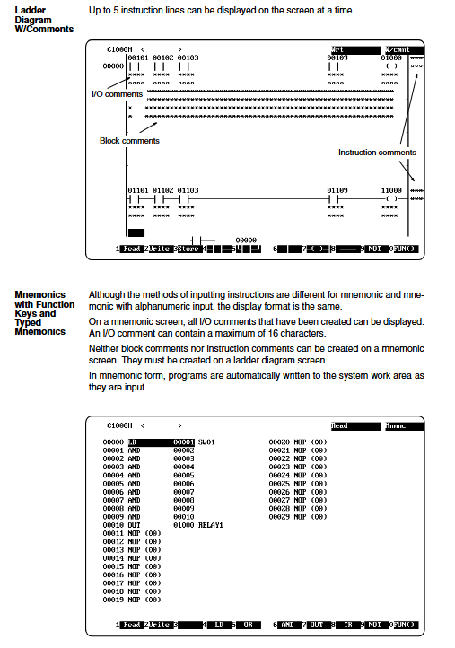
Offline programming: mnemonic mode
The mnemonic mode provides a lower level programming interface, suitable for engineers who are accustomed to text programming.
4.1 Two input methods
The mnemonic screen supports two input styles:
Function key input: Use the function key prompts at the bottom of the screen, combined with the Ctrl key to enter the address prefix (such as Ctrl+F4 to enter DM).
Typing input: Directly enter mnemonics (such as LD, AND, OUT) and operands through the keyboard. Please note that mnemonics and operands must be separated by a space.
4.2 Automatic Storage Features
Unlike ladder diagram mode, instructions entered in mnemonic mode are automatically written into the system workspace without the need for manual storage operations. This makes small-scale quick modifications extremely efficient.
4.3 Search and Editing
In mnemonic mode, code snippets can be quickly located by inputting program addresses, instruction mnemonics, or bit addresses. When editing, simple intra line insertion and deletion are supported, and the modified program needs to run a “program check” to confirm logical correctness.
I/O Table Editing and Configuration
The I/O table is a key data structure for the CPU to identify various units connected to the rack, such as input modules, output modules, and special I/O units. For PLCs such as C20, P-type, K-type, and CQM1, I/O tables are not required, but for large PLCs, this step is crucial.
5.1 I/O Table Creation Logic
In offline mode, users can manually build I/O tables. The rack number is displayed on the left side of the screen, and the slot and configuration information are displayed on the right side.
Basic I/O: Use the F1 (output) and F2 (input) keys to allocate slots.
Special I/O Unit: Press the F8 key to enter the unit number (0-9 or 0-F, depending on the model) and unit type code (such as C for high-speed counter and N for position control unit).
Remote I/O: Configure remote racks through F4 (master) and F6 (slave).
5.2 Error checking
After configuration is complete, you must press the F10 key to exit and write to the workspace. The system will automatically check the I/O table, and common errors include:
Word over: The allocated word count exceeds the limit.
Duplicate word: The same word address is assigned to multiple units.
IN/OUT mix: Contains both input and output points in the same word (not allowed for some models).
Data Storage Area (DM) Editing
The DM area is used to store operational data and PC settings parameters.
6.1 Data Display and Input
The DM display interface consists of 160 words per page, displaying both hexadecimal and ASCII code content simultaneously. Users can press A: HEX ↔ ASCII key switches input mode.
Hexadecimal input: Enter a 4-digit hexadecimal number directly.
ASCII input: Enter the corresponding character code.
6.2 Data Operations
Copy: DM data within a specified range can be copied to another area.
Fill: Fill a specific value into a specified range, commonly used for initialization (fill in 0000).
Save and Retrieve: DM data can be saved independently of program files, with a file extension of SP6 (Save All) or SL4 (block saving).
Practical program operation
The utility menu provides advanced tools for maintenance and debugging.
7.1 Global Address Modification
When the on-site I/O points change, manually modifying every address in the program is extremely cumbersome. The global address modification function provided by SSS can be completed with one click:
Address modification: Replace all IR 00001 in the program with IR 00003, and choose whether to replace I/O comments at the same time.
Word address modification: Batch modify word addresses and timer/counter numbers.
Range setting: Supports the replacement of continuous address ranges, greatly improving program porting efficiency.
7.2 EPROM Operation
In situations where program solidification is required, SSS supports burning chips through EPROM writers.
Chip selection: Choose the chip capacity based on the PC model (such as 2764, 27128, etc.). Large PLCs such as C1000H/C2000H typically require paired use of ROM chips (parity chips).
Writing process:
Select T: Computer ↔ ROM。
Set the EPROM capacity.
Select W: Write.
The system converts the program into an intermediate language and writes it to the ROM data buffer, then prompts to start writer burning.
Intel HEX files: SSS can also be generated HEX standard format file for use by third-party programmers.
7.3 PC Settings
For models such as CQM1 and C200HS, the operating parameters can be set through software and stored in the DM 6600-6655 area
Startup mode: Set the operating mode after power on (programming, monitoring, or running).
RS-232C settings: Configure serial communication parameters (baud rate, parity, etc.).
Cycle time monitoring: Set the maximum cycle scanning time, and if it exceeds the time limit, an alarm will be triggered.
Print output and document archiving
SSS supports rich printing functions to help generate technical documents:
Ladder chart printing: You can set the number of lines per page, printing range, and whether to include annotations. Support printing X/Y labels to distinguish input and output points.
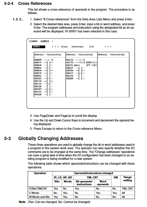
Cross reference table: Printing all reference positions of a specific address in the program is an important basis for troubleshooting logical errors.
Mnemonic List: Print command list and program address.