SEW EURODRIVE MOVIDRIVE ® MD-60A series frequency converter
Overview
Name: MOVIDRIVE ® MD_60A Operating Instructions
Core purpose: To guide the safe installation, start-up, operation, and maintenance of this series of frequency converters, suitable for driving AC asynchronous motors or permanent magnet synchronous motors in industrial and commercial systems (requiring adaptation to frequency converters)
Prohibited use scenarios:
Explosion-proof area
Exposure to harmful oils, acids, gases, dust, radiation, and other environments
Non fixed applications with mechanical vibrations and impacts exceeding the requirements of EN 50178
Safety and Equipment Fundamentals
Security level and consequences
Possible consequences of hazardous types
Serious electrical hazards or fatal injuries
Ordinary danger, serious or fatal injury
Minor injury in dangerous scenarios
Harmful scenario equipment or environmental damage
Equipment identification and specifications
Unit model interpretation: including information such as power, voltage, power supply type, filtering configuration, etc MDV 60 A 0055-5A3-4-00:5.5kW、380-500V、 3-phase, with brake chopper)
Size classification: There are a total of 5 sizes corresponding to different power ranges (1-2: low power, 3-5: high power)
Standard accessories:
Size 1/2: Signal terminal connector, power shielding clip
Size 4/5: Power terminal protective cover (up to IP10 protection after installation)
Installation requirements
Basic installation parameters
Specific standards for required types
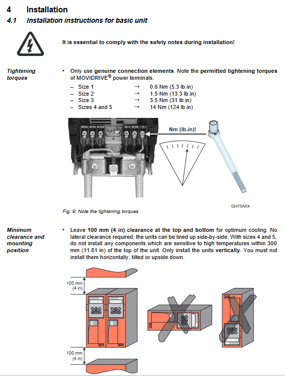
Tightening torque size 1: 0.6 Nm; size 2: 1.5 Nm; size 3: 3.5 Nm; size 4/5:14 Nm
Installation spacing top/bottom ≥ 100mm; size 4/5, no high temperature sensitive components within 300mm of the top
The installation posture should only be vertical, and horizontal, inclined, or inverted installation is prohibited
Cable requirements: Power cables and electronic cables should be routed in separate slots; Electronic cable single core 0.2-2.5mm ², dual core 0.2-1mm ²
Wiring and Protection
Grounding requirements: The cross-section of the PE conductor should match the power line (when ≥ 10mm ², it should have the same cross-section as the power line)
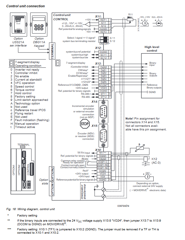
Bus connection:
SBus: Up to 64 nodes, cable length varies with baud rate (320m at 125kbaud)
RS-485: Up to 32 units, cable length ≤ 200m
EMC protection: Standard input filter (Class A) for size 1/2, optional for size 3-5; Shielded cable and output reactor (HD series) are required on the motor side
Start the process
Starting premise
Complete installation inspection to prevent accidental motor start-up (such as disconnecting X13 terminal block)
Preset parameters: Restore factory settings or configure parameters according to application settings
Startup method
Key points for operating the applicable mode of startup mode
DBG11A keyboard VFC mode requires input of motor model, rated voltage/frequency, encoder type and other data, supporting speed controller startup
MOVITOOLS software VFC/CFC/SERVO mode connection USS21A option (RS-232/RS-485), supports asynchronous/synchronous motor settings, and can batch copy parameters
Motor starting method
Analog quantity given: Input 0-10V or 4-20mA signal through AI1 terminal
Fixed setting value: Select preset speed (n11/n12/n13) through DI terminal combination
Manual operation: DBG11A keyboard control, 7-segment code displays “H”, speed adjustment speed is 150rpm/s
Operation and maintenance
Operation display
7-segment code display: There are a total of 16 states (such as “0”=not ready, “F”=fault flashing, “H”=manual mode)
DBG11A keyboard: supports parameter copying, language switching (German/English/French), and quick menu operations
Fault handling
Fault storage: Record the last 5 faults (including status, current, temperature, and other information)
Reset methods: Power off restart, terminal reset, software reset (P840), automatic reset (P841, up to 5 times)
Common faults: overcurrent (01), grounding fault (03), DC bus overvoltage (07), encoder fault (14), etc., with specific troubleshooting measures attached
Parameter Settings
Core parameter categories: display value (speed/current, etc.), set value/ramp (speed range -5000~5000rpm), controller parameters, monitoring function, terminal allocation
Key parameters: P700 (operating mode), P302 (maximum speed), P835 (TF signal response)
Technical data
Core electrical parameters (400/500V series example)
Size Power Range (kVA) Rated Current (AAC) Cooling Air Consumption (m ³/h) Weight (kg)
1 2.8-6.6 4.0-9.5 40 3.5
3 22.2-41.6 32-60 180 15
5 73.5-91.0 105-130 360 35
Environment and Protection
Working temperature: 0-50 ℃ (100% load), 0-40 ℃ (125% load)
Storage temperature: -25~70 ℃
Installation height: ≤ 1000m (over 1000m, capacity reduction of 1% per 100m)