SEW EURODRIVE MOVITRAC 31C series frequency converter
The operating manual for SEW EURODRIVE’s MOVITRAC 31C series frequency converter (July 2000 version) covers safety specifications, installation requirements (including EMC/UL compliance), start-up process (FBG31C keyboard/MC_SHELL software operation), operation and maintenance (troubleshooting, parameter configuration), and technical data. It is suitable for driving three-phase AC squirrel cage asynchronous motors, providing four sizes from 0-4 and two voltage specifications of 230V/400-500V. It supports three start-up modes: analog/fixed value/manual, and is equipped with multiple tabs such as FEA31C (IO extension) and FEN31C (speed detection). It clearly prohibits the use in explosion-proof areas and non fixed vibration scenarios, and must strictly follow the wiring specifications and Reduce capacity rules to ensure safe and stable operation.
Safety and Equipment Fundamentals
Security level and requirements
Specific requirements for safety types
Operation qualifications only allow trained professionals to install, start, and maintain
Electrical protection must be grounded and equipped with overcurrent protection devices (fuses). Even after a power outage, there may still be dangerous voltage within 10 minutes
Operation safety prohibits individual responsibility for personnel/equipment safety functions; Fault reset may cause the motor to restart, and the power supply needs to be disconnected in advance
The protection level of the whole machine is IP20 (EN 60529), and after removing the front cover, it is IP00. It needs to be kept closed during operation
Equipment identification and specifications
Model interpretation: Taking MOVITRAC 31C110-503-4-00 as an example, 110=11kW (recommended motor power), 50=380-500VAC, 3=three-phase, 4=4-quadrant (with brake chopper), 00=standard version
Size classification: There are a total of 5 sizes (0-4), corresponding to a power range of 0.55kW-45kW. Size 0 has no option slot, and 1-4 supports X20/X21 tab expansion
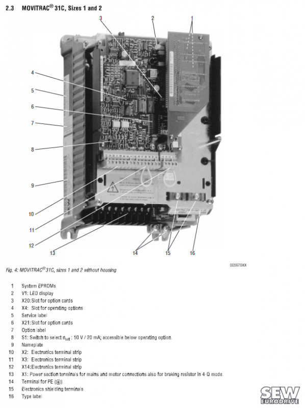
Standard accessories: power terminal, PE terminal, electronic terminal block, LED status indicator light (V1), S1 signal selection switch (10V/20mA)
Installation requirements
Mechanical installation parameters
Specific standards for required types
Tightening torque size 0:1.5 Nm; size 1:0.6 Nm; size 2:1.5 Nm; size 3/4:3.5 Nm
Installation spacing top/bottom ≥ 100mm, no lateral spacing requirement
The installation posture should only be vertical, and horizontal, inclined, or inverted installation is prohibited
Environmental conditions: Operating temperature 0-45 ℃ (rated load), capacity reduction of 3%/K at 45-60 ℃; Storage temperature -25-70 ℃
Electrical Installation Specification
Cable requirements:
Power cable: Select according to the rated input current, and when the PE conductor cross-section is ≥ 10mm ², it should have the same cross-section as the power line
Motor cable: selected according to the rated output current, with a maximum length of 100m, shielded twisted pair cable, and shielded layer grounded at both ends
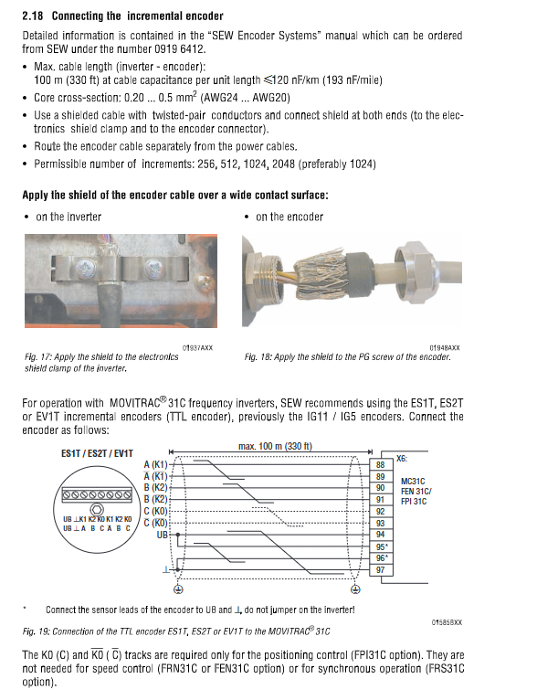
Encoder cable: Core wire cross-sectional area of 0.2-0.5mm ², maximum length of 100m, routed in separate slots with power cables
Grounding requirements: The casing of the frequency converter should be in metal contact with the installation plate of the switchgear, and the PE conductor should be reliably grounded
EMC protection:
Input side: Configure NF series input filter, installed at a distance of ≤ 400mm from the frequency converter
Output side: Equipped with HD series output reactors, only U/V/W three-phase pass through the reactors, PE conductors do not pass through
UL Compliance Requirements
Specific standards for compliance items
The wire material only uses copper wire, with a temperature rating of 60/75 ℃ or 75 ℃ (depending on the model power)
Fuse selection: 230V model, maximum 63-110A/600V; 400-500V model, maximum 16-400A/600V
The power supply system is only applicable to TN/TT systems, and the IT system does not have UL certification
External 24V power supply voltage ≤ 30VDC, current ≤ 8A
Tab and Interface Configuration
Core tab functionality
Tab Model Function Installation Slot Key Parameters
FEA31C Analog/Digital IO Expansion X20 2-channel Analog Input, 2-channel Analog Output, 4-channel Binary Input
FIO31C digital IO expansion X20 with 7 binary inputs and 6 binary outputs
FEN31C speed detection X21 supports incremental encoders with a maximum pulse frequency of 200kHz
FPI31C position detection X21 supports SSI absolute encoder, 128-2048 pulses/rev
FIT31C motor temperature detection (TF/TH) X21 binary output indicates motor temperature status, triggering emergency stop when overheating occurs
USS21A serial interface extension X4 supports RS-232 (up to 5m), RS-485 (up to 200m, 32 nodes)
Interface technical data
RS-232 interface: baud rate 9600baud, 8 data bits+1 stop bit, no checksum, 9-pin D-type connector
RS-485 interface: baud rate 9600baud, half duplex asynchronous, 4-core shielded cable, integrated terminal resistor
Start the process
Starting premise
Complete installation inspection, disconnect electronic terminal block X3 to prevent accidental motor start-up
Choose the startup tool: FBG31C keyboard (direct operation) or MC_SHELL software (PC connection)
Core startup steps (FBG31C keyboard)
Step operation content
Connect the keyboard to the X4 slot, and the LED V1 will turn yellow (ready state) when powered on
Select language (German/English/French) and set it through P850 parameters
3. Basic configuration parameters: P200 (minimum frequency 5Hz), P201 (reference frequency, according to the motor nameplate), P202 (maximum frequency)
4. Activate the frequency converter: X3:43 (enable/emergency stop) connected to the “1” signal
5. Starting motor: X2:41 (forward rotation) or X3:42 (reverse rotation) connected to the “1” signal, the motor starts at the P200 set frequency
6 Optimization Parameters: Adjust Slope Time (P120/P121), BOOST (P321), I × R (P322), etc
Motor starting method
Key operating points for applicable scenarios of startup mode
Analog continuous speed regulation is given by inputting 0-10V or 4-20mA signals through X2:34 terminals
Fixed set value multi speed control selects P160-P162 (n11/n12/n13) preset frequency through binary input combination
Enable P870 (manual operation) in the manual operation debugging scenario, and adjust the speed (150rpm/s) through the ↑/↓ keys on the keyboard
Operation and maintenance
Operation display
LED indicator status:
Meaning of LED color status
Yellow ready (mains power supply is normal)
Green rotating magnetic field activation (motor operation)
Red fault alarm
Yellow flash self-test/factory reset/undervoltage
Red yellow flashing limit switch activated
FBG31C keyboard: supports parameter copying, fault viewing, manual operation, provides short menu (common parameters) and full menu (full parameters)
Fault handling
Fault storage: P060-P064 records the last 5 faults, including data on DC bus voltage, heat sink temperature, current, etc. at the time of the fault
Reset method: Power off restart (required ≥ 10 seconds), terminal reset (programming binary input is “reset” function), keyboard E key reset, software reset
Common faults and solutions:
Fault code description and troubleshooting measures
1. Overcurrent check for output short circuit, motor overload, and output stage fault
2 DC bus overvoltage extension deceleration ramp, check the brake resistor wiring
6. Overheating improves heat dissipation, reduces load, and checks the fan
10. Incorrect rotation direction. Switching motor two-phase wiring
50 limit switch missing check limit switch wiring, short circuit if not in use
Core parameter configuration
Motor parameters: P320 (maximum current 150% rated value), P324 (pole pairs, 4-pole motor set to 2), P329 (motor voltage)
Control parameters: P120 (ramp rise time 1-2000s), P201 (reference frequency 50/60Hz), P770 (operating mode: V/f/speed control)
Protection parameters: P510 (speed monitoring), P541 (motor protection: alarm/stop)
Technical data (core specifications)
Core parameters of 230V model (example)
Model size, rated output power, rated output current, minimum resistance of braking resistor
005-233 0 1.3kVA 3.2AAC 68Ω
022-233 1 3.4kVA 8.6AAC 33Ω
075-233 3 11.6kVA 29AAC 11Ω
Core parameters of 400-500V models (example)
Model size, rated output power, rated output current, minimum resistance of braking resistor
011-503 0 2.2kVA 3.2AAC 200Ω
055-503 2 8.3kVA 12AAC 47Ω
220-503 3 33kVA 47AAC 15Ω
electronic data
Analog input: 9-bit resolution (voltage)/8-bit resolution (current), sampling time 5ms
Binary input: Optocoupler isolation, 13-30V=1, -3-5V=0, sampling time 5ms
PWM frequency: 4/8/12/16kHz adjustable (P325)
Auxiliary power output: 24VDC, maximum 250mA