Moog G77X/-77X series high-performance flow control servo valve
Product positioning and structure
G77X/-77X is a two-stage flow control servo valve of Muge industrial grade. It adopts a closed center four-way slide valve main stage and a symmetrical dual nozzle baffle pilot stage. It is driven by a dual air gap dry torque motor and a cantilever spring to achieve mechanical feedback of the valve core position. The structure is sturdy, the service life is long, and the reliability is high.
Applicable scenarios: high-precision electro-hydraulic position, velocity, pressure, force closed-loop control system
Explosion proof version: certified by FM, ATEX, CSA, TIIS, IECEx, suitable for use in hazardous locations
Model and installation specifications
Model Installation Standard Maximum Flow Interface Aperture
G771/771 ISO 10372-02-02-0-92 17 l/min 4.85 mm
G772/772 ISO 10372-03-03-0-92 57 l/min 6.63 mm
G773/773 Muge exclusive 63 l/min 7.92 mm
Core performance parameters
Hydraulic parameters
Maximum working pressure: 210 bar (3000 psi) (universal for P/A/B/T ports)
Rated pressure drop: 35 bar/spool shoulder
Rated flow rate: 4, 10, 19, 38, 57 l/min
Internal leakage rate: maximum 1.9 l/min (zero overlap)
Oil: DIN 51524/ISO 11158 hydraulic oil
Viscosity: 10~97 mm ²/s (recommended), 5~1250 mm ²/s (allowed)
Dynamic/static indicators
Step response (0~100% travel): 4/4/4/10/17 ms
Threshold: ≤ 0.5% rated signal
Hysteresis: ≤ 3.0% rated signal
Temperature drift (Δ T=38 ℃): ≤ 2.0% rated signal
Environment and Machinery
Working temperature: -40~+135 ℃
Storage temperature: -40~+60 ℃
Vibration resistance: 30 g, 10-2000 Hz
Impact resistance: 30g, 3-axis
Weight: 0.86 kg
Sealing: FKM (Viton B) 90 Shore
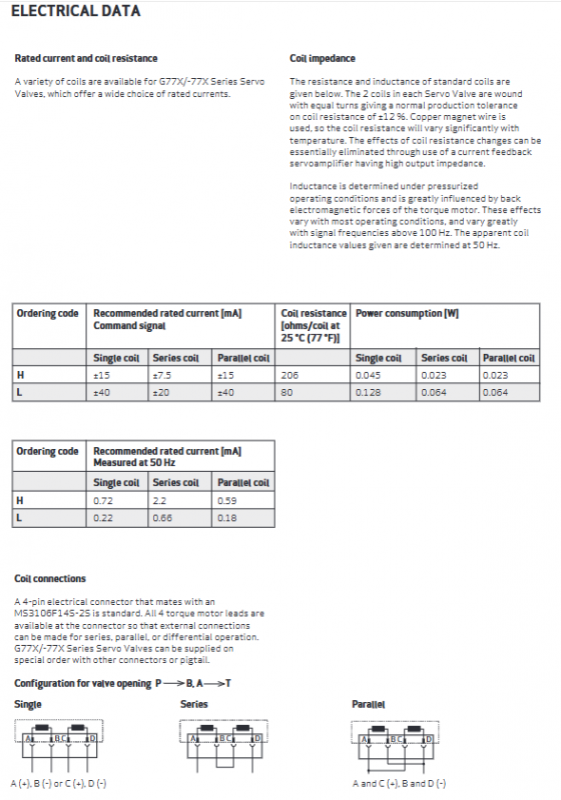
Electrical parameters
Coil specifications: H-type (± 15mA), L-type (± 40mA)
Coil connection method: single coil/series/parallel
Standard connector: 4-pin MS3106F14S-2S
Power consumption: 0.023~0.128 W
Working principle
Electrical signal input → Torque motor drives armature/baffle deflection
Pressure difference change of nozzle baffle → driving the main valve core to move
The valve core drives the feedback spring to generate force balance → the valve core stabilizes at the corresponding opening
The output flow rate is proportional to the input electrical signal, achieving precise flow control
Adjustment and installation
Zero adjustment: Mechanical eccentric sleeve adjustment, range * * ± 10% * * rated flow, requires 3/8 “wrench+3/32” hexagon socket
Flow formula: Q=QN × √ (Δ P/Δ PN)
Valve core form: Standard shaft cut, positive overlap, negative overlap optional
Installation surface flatness: ≤ 0.05 mm/100mm, roughness Ra ≤ 0.8 μ m
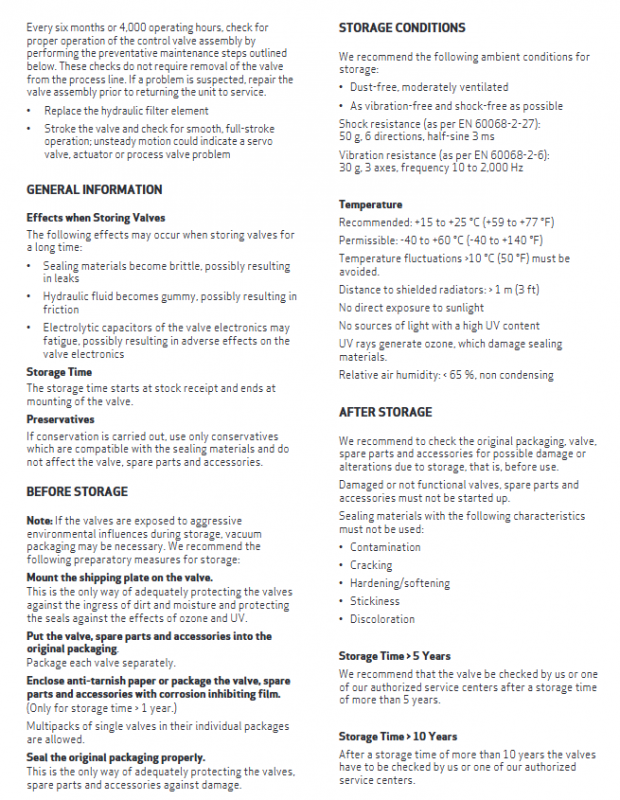
Maintenance and Storage
Routine maintenance: Replace the filter element every 6 months or 4000 hours, and conduct a full stroke motion test
Storage conditions: -40~60 ℃, humidity<65%, dust-proof and vibration proof, vacuum packaging
If stored for more than 5 years, it needs to be returned to the factory for testing, and if stored for more than 10 years, it must be tested
Matching and ordering
Accessories: installation bolts, flushing plate, matching joints, servo amplifier
The ordering code includes: model, flow rate, pressure, valve core, pilot, connector, seal, signal, etc
Preferred models: G771-3001A/3002A, G772-3003A/3004A, G773-3005A