Schneider C60H-DC C-curve DC supplementary protector
Product positioning and standards
Product Usage
Used for short-circuit protection, overload protection, control and isolation of DC circuits, suitable for industrial control, automation, transportation, and new energy systems.
Belongs to supplementary protector, TC 3 category.
execution standard
IEC/EN 60947‑2、UL1077、GB 14048.2
Core electrical specifications
1. Voltage and number of poles
Specification 1P 2P
Rated working voltage Ue 12… 250V DC 12… 500V DC
Rated voltage Un 250V DC 500V DC
Width 2 molds (9mm) 4 molds (9mm)
2. Breaking ability
table
Voltage 1P breaks 2P breaks
110V DC — 20kA
220V DC — 10kA
250V DC 5kA 6kA
440V DC — 10kA
500V DC 5kA 6kA
3. Release characteristics
Curve type: C-curve
Magnetic release range: 7In~10In (standard value 8.5In ± 20%)
Category: Class A (No Delay)
4. Key electrical parameters
Rated insulation voltage Ui: 500V DC
Impact withstand voltage Uimp: 6kV
Mechanical lifespan: 20000 cycles
Electrical lifespan: 3000 cycles for inductive circuits; Resistive circuit 6000 times
Environmental and physical parameters
Working temperature: -25 ℃~+70 ℃
Storage temperature: -40 ℃~+85 ℃
Humidity: 95% (55 ℃, no condensation)
Pollution level: 3
Weight: 1P ≈ 128g; 2P≈256g
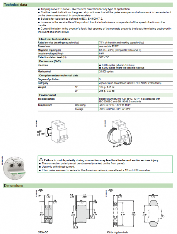
Wiring and safety requirements
Polarity must be strictly distinguished, and reverse connection may cause fire/electric shock.
Both upward and downward wires can be used, and the polarity must be consistent.
When 2P series is used for American systems, the cable length is ≥ 30cm.
Tightening torque:
≤25A:2.5N·m
>25A:3.5N·m
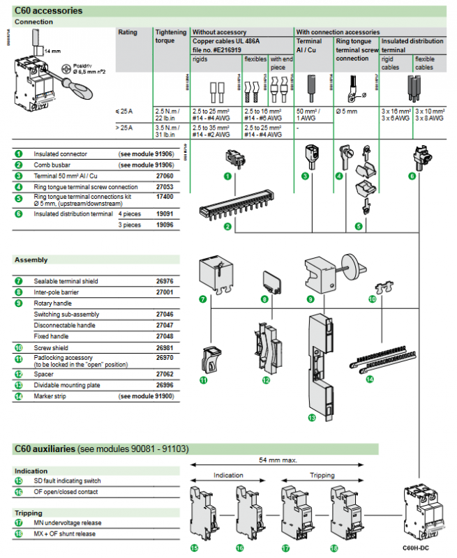
Attachment system
Instructions and release attachments
SD: Fault indicator contact
OF: Position auxiliary contact
MN: Under voltage trip
MX: Split excitation release
Installation and wiring accessories
Insulated connectors, comb shaped busbars, high current terminals, ring terminals, inter electrode partitions, lockable handles, marking strips, etc.
The attachment is installed on the left side of the circuit breaker, with a total width of ≤ 54mm.
Extreme configuration and fault protection
24V~250V: Prioritize 1P (grounding polarity) or 2P full protection.
250V~500V: 2P must be used.
Different grounding systems have different fault types (A/B/C) and protection polarity requirements, which require corresponding breaking capacity.
Temperature reduction
Provide a complete temperature rated current comparison table, with a significant reduction in rated current at 70 ℃.
Multiple units installed side by side require a capacity reduction factor of 0.8.
Key issues
Question 1: What is the C-curve tripping characteristic of C60H-DC? What faults are mainly protected?
answer
The magnetic trip interval of the C-curve is 7In~10In (standard 8.5In ± 20%).
Mainly achieve two types of protection:
Overload protection: thermal trip, slow disconnection due to long-term overcurrent.
Short circuit protection: Magnetic trip, instantaneous disconnection due to high current.
Simultaneously equipped with isolation function, meeting the safety disconnection requirements of IEC standards.
Question 2: What are the core differences between P and 2P models in terms of voltage, breaking capacity, and application scenarios?
answer
1P: Maximum 250VDC, breaking 5kA, width of 2 modes, used for grounding polarity single pole protection (24-250V system).
2P: up to 500VDC, breaking up to 20kA, width of 4 modes, used for ungrounded systems/high voltage DC (250~500V), while protecting the positive and negative poles.
Simple rule: 1P is available for ≤ 250V; 2P is required for > 250V.
Question 3: Why must polarity be strictly followed when wiring? What are the consequences of reversing? How to avoid it?
answer
Reason: The DC arc extinguishing and breaking structure is designed according to polarity, and reverse connection can cause arc extinguishing failure and breaking failure.
Consequence: Short circuit cannot be disconnected → Fire, explosion, equipment burning, personal injury.
Avoidance methods:
Strictly follow the panel * * ± label * * for wiring.
Both upward and downward movements are acceptable, but the polarity cannot be reversed.
Double check the polarity after wiring.