Yaskawa ∑ – II series SGMBH servo motor+SGDH servo driver
Product basic information
Product combination: Yaskawa ∑ – II series SGMBH servo motor+SGDH servo drive
Voltage level: 400V level (380-480VAC)
Power range: 22kW/30kW/37kW/45kW/55kW
Encoder: incremental/17 bit/20 bit absolute
Manual Number: SIE-S800-32.42002 Edition
Applicable: High power, high-precision positioning, speed/torque control equipment
Safety regulations (mandatory)
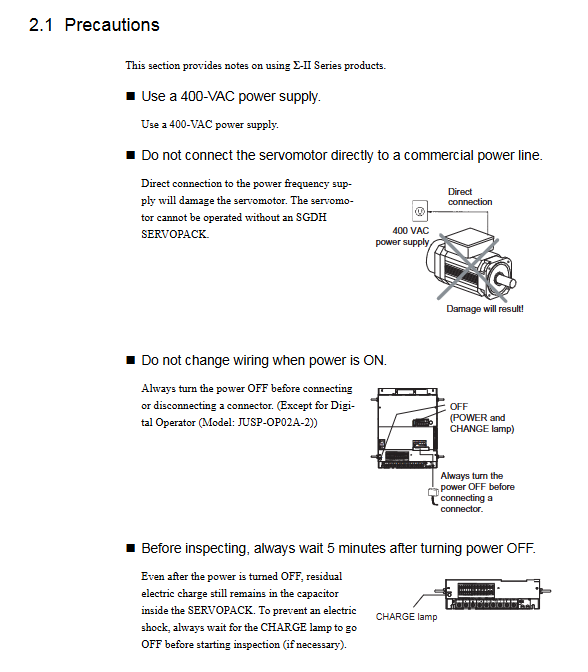
After power failure, wait for 5 minutes to confirm that the CHARGE light is off before operating
Grounding resistance * * ≤ 100 Ω * *, single point grounding
The motor is cooled by a fan and must be equipped with overheat protection
Prohibit direct connection of mains power to motor U/V/W
Do not plug or unplug connectors with power on (except for operators)
Installation requirements
Project requirements
Vertical installation of directional driver
Spacing up and down ≥ 50mm, left and right ≥ 10mm
Environmental temperature 0-55 ℃, no condensation, no dust
Radial/axial loads are limited by the model and cannot be overloaded
Used indoors, oil proof, waterproof and foggy
Wiring Core
1. Main circuit terminal
L1/R, L2/S, L3/T: three-phase 400V input
U. V, W: Output connected to motor
B1/B2: External braking resistor
DC24P/DC24N: Control power supply
2. CN1 (50 pin I/O core)
/S-ON (40 pins): Servo enable (low level effective)
P-OT (42)/N-OT (43): forward/reverse overtravel prohibited
/ALM-RST (44): Alarm reset
V-REF (5): Given speed analog quantity
T-REF (9): Given torque analog quantity
PULS/IGN (7/11): Position pulse command
ALM+/ALM – (31/32): Alarm output
PAO/PBO (33/35): Encoder Divided Output
3. CN2: Encoder interface
Incremental: A/B/Z signals
Absolute formula: Battery backup (BAT+/BAT -), no need to reset to zero
Control mode (Pn000.1 selection)
Speed Control (0): Analog ± 10V Given
Position control (1): Pulse train command
Torque Control (2): Analog Torque Limiting
Multi speed control (3-6): Terminal selection for 3-speed control
Mode switching (7-9/B): Position/speed/torque switching
Zero clamp position (A): Positioning lock when stopped
Core parameter system
1. Pn parameters (function/gain/gear)
table
Typical values of parameter functions
Pn000.1 Control mode selection 0/1/2
Pn100 speed loop gain 40Hz
Pn102 position loop gain –
Pn202/203 electronic gear numerator/denominator 1-65535
Pn402/403 forward/reverse torque limit 0-800%
Pn506 brake delay 0-50
2. Fn auxiliary function
Fn008: Absolute value encoder reset to zero
Fn013: Multi turn limit setting
JOG operation, origin search
3. Un monitoring
Un000: Actual rotational speed
Un005/006: I/O status, torque monitoring
Trial operation process (two-step method)
Step 1: No load trial operation
Disconnect the load and check the wiring
Operate the JOG operator and confirm the steering, noise, and vibration
Step 2: On load trial operation
connection load
Perform automatic tuning
Confirm positioning, response, and alarm
Key functions
Electronic gear: any pulse equivalent, no mechanical speed change required
Absolute value encoder: power-off memory position, no need to return to zero when turned on
Brake control: vertical axis anti drop, timing can be set
Torque limit: protect machinery and prevent overload
Auto tuning: Automatically identify load inertia and optimize gain
Overtravel protection: P-OT/N-OT hard limit
Alarm and maintenance
Alarm format: A.xx (such as A.41 undervoltage, A.81 encoder battery)
Alarm output: ALM disconnected, ALO1- ALO3 output fault code
Vulnerable parts: encoder battery, fan, braking resistor
Maintenance: Regularly check wiring, heat dissipation, grounding, and screw torque
Key issues
Question 1: What are the three main control modes of SGDH drivers? What signals are given separately?
answer:
Speed control: given by CN1-5 V-REF analog ± 10V;
Position control: given by CN1-7/11 PULS/IGN pulse train;
Torque control: Given and limited by CN1-9 T-REF analog quantity.
Switch modes based on parameter Pn000.1.
Question 2: What are the advantages of absolute value encoders? What wiring and settings should be noted?
answer:
Advantages: Save location during power outage, no need to reset to zero during startup, improving efficiency.
Wiring: * * CN1-21/22 BAT+/BAT – * * backup battery must be connected;
Setting: Pn002.2=0 Enable absolute value, use Fn008 to reset multi cycle data.
Question 3: Which pin corresponds to CN1 for servo enable, overtravel, and alarm reset? What is logic?
answer:
Servo enable/S-ON: CN1-40, low level effective;
Overtravel P-OT/N-OT: CN1-42/43, high level operation prohibited;
Alarm reset/ALM-RST: CN1-44, low level reset.