Siemens SIMATIC S5-90U/S5-95U Compact PLC
The official system manual for SIMATIC S5-90U/S5-95U compact PLC released by Siemens comprehensively covers product positioning, hardware design, installation and wiring, startup and debugging, STEP 5 programming, diagnosis and troubleshooting, I/O addressing, and communication networking processes. It specifies that S5-90U is an economical basic model and S5-95U is a high-performance enhanced model, supporting S5-100U module expansion, STEP 5 language programming, SINEC L1/L2 network communication, providing complete hardware specifications, wiring specifications, fault diagnosis methods, and module selection lists. It is a comprehensive guidance document for both PLCs from design to operation and maintenance.
Product positioning and hardware differences
Model Core Positioning Board I/O Memory Timer/Counter Features
S5-90U economical basic PLC 10 in 6 out 4KB 32/32 basic logic, 1-channel counter/interrupt
S5-95U high-performance enhanced PLC 16 in 16 out+8 analog inputs+1 analog output 16KB 128/128 PID, real-time clock, dual counter, time control program
Scalability:
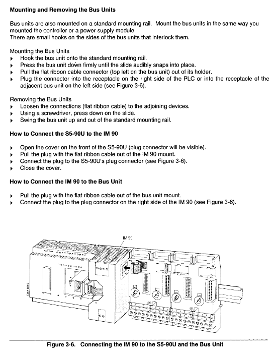
S5-90U: IM90 interface module is required, up to 6 S5-100U modules can be connected
S5-95U: Direct expansion, up to 32 S5-100U modules can be connected
power supply
S5-90U: 115/230V AC direct power supply
S5-95U: 24V DC power supply, can be equipped with PS931 power module
Installation and wiring specifications
Installation method
Standard: 35mm DIN rail installation, supports wall mounting
Expansion: Up to 4 layers of rack, connected with IM315/IM316
Spacing: Vertical installation spacing ≥ 210mm, ambient temperature ≤ 40 ℃
Wiring requirements
Terminal: screw terminal, SIGUT double terminal, crimping terminal
Wiring: Separate wiring into A/B/C groups, simulate and shield communication lines
Grounding: equipotential connection, copper wire cross-sectional area ≥ 16mm ²
Analog/high-speed signals: Shielded cables must be used, with a single end grounded
Operation mode and startup process
working mode
STOP: Program stops, output disabled, data preserved
RUN: Loop program execution, running normally
REST: Restart, load DB1 parameters, execute OB21/OB22
Startup steps
Power off inspection of machinery and wiring
Connect the power supply and switch to STOP
Insert the battery and perform a power on self-test
Loading program (EEPROM automatic/manual)
Switch to RUN, test I/O and logic
Total reset (clearing program)
S5-90U: Power off → Remove battery → Wait for 15 seconds → Power on → Install battery
S5-95U: STOP → Remove battery → Turn off power → Turn on power → Install battery

STEP 5 Programming Core
Programming method: STEP 5, supports statement tables, ladder diagrams, and functional diagrams
Program Structure: Organizational Block OB, Program Block PB, Function Block FB, Data Block DB
core functionality
Interrupt input: 90U (1 point), 95U (4 points), OB3 processing
Counter: 90U (1-channel 1kHz), 95U (2-channel, up to 5kHz, supports 32-bit cascading)
Analog quantity: 95U comes with 8 inputs and 1 output, processed by FB250/FB251
Advanced features: 95U built-in PID algorithm (OB251), real-time clock
Diagnosis and troubleshooting
status indicator
RUN (green): Running
STOP (red): stop/malfunction
BF (yellow, only 95U): Battery failure
diagnostic tool
Diagnostic byte IB35: Monitoring interrupts, count overflow, power, battery status
ISTACK: Interrupt stack, check the cause of the fault (power, program, I/O errors)
BSTACK: Block Stack, Tracking Program Call Flow
Common Faults
Unable to switch RUN: Program error, I/O not ready, power exception
Program loss: battery failure, not backed up to EEPROM
I/O exception: wiring error, address error, module not encoded
Communication and Expansion Module
communication
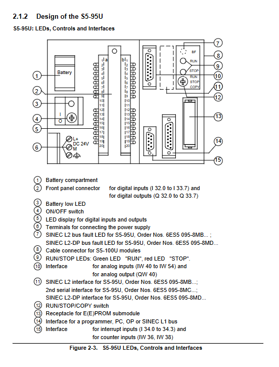
Programming port: 15 pin 20mA TTY, connected to programmer/OP
Network: SINEC L1 (90U/95U), SINEC L2/DP (95U optional)
Protocol: 3964 (R), ASCII, PLC Link
Module Type
Digital quantity: input, output, hybrid module
Analog quantity: Analog input/output module
Functional modules: high-speed counting, positioning, closed-loop control, communication processor
Key questions and answers
Question 1: What are the differences in core hardware and functionality between S5-90U and S5-95U?
answer:
S5-90U: Economy entry-level model, 115/230V AC power supply, onboard 10 in 6 out, 4KB memory, 32 timers/counters, only supports basic logic and 1 counter/interrupt, requires IM90 to expand module.
S5-95U: High performance enhanced version, powered by 24V DC, onboard 16 in 16 out+8 analog in+1 analog out, 16KB memory, 128 timers/counters, built-in PID, real-time clock, dual high-speed counters, can directly expand up to 32 modules.
Question 2: How to backup and restore the programs of S5-90U/S5-95U?
answer:
Backup: Save the program to the EEPROM submodule. For S5-90U, use the COMPRESS programmer. For S5-95U, press and hold the COPY button for 3 seconds.
Recovery: Power off and insert EEPROM → Power on, automatic loading; S5-95U can be manually forced to load by pressing and holding the COPY button to power on.
Power outage maintenance: Relying on lithium batteries, RAM data is lost after power outage when there is no battery.
Question 3: Common reasons and troubleshooting methods for PLC unable to switch to RUN mode?
answer:
Common reasons
Program error or no valid program
External I/O module not ready or faulty
Abnormal power supply, battery failure
Scan time timeout, block stack overflow
troubleshooting method
Check the flashing/steady state of the red LED
Using a programmer to read ISTACK and locate the fault type
Reload the program after executing the overall reset
Check the coding, wiring, and power supply of the I/O module