
ABB Procontic CS 31 Distributed Automation System Description
System Overview
CS 31 is a decentralized intelligent automation system with RS485 master-slave bus as its core, used to replace centralized control cabinets and significantly reduce wiring costs.
Communication: RS485 half duplex, 187.5k baud rate
Topology: 1 master station+up to 31 slave stations
Distance: The maximum length of a single bus segment is 500 meters (the amplifier can be expanded up to 2km)
Advantages: Reducing wiring by up to 80%, module hot swapping, automatic identification and expansion
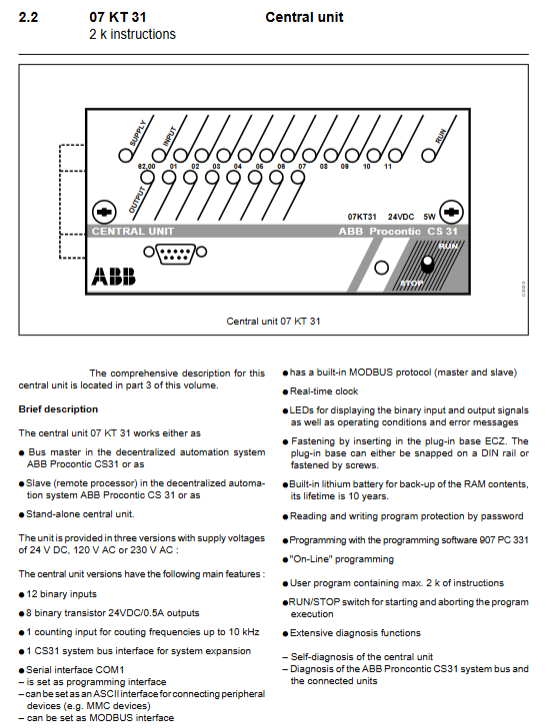
CPU central unit (core model)
Model, Program, Capacity, Key Characteristics, Power Supply
07 KR 31 2K 12DI+8 relay output, 10kHz counting 24VDC/120/230VAC
07 KT 31 2K 12DI+8 transistor output, 10kHz counting 24VDC/120/230VAC
07 KR 91 7K 20DI+12 relay RS232、 Clock 24VDC/120/230VAC
07 KT 92 14K 12DI+8 transistor, 4AI+2AO, PID, 50kHz 24VDC
07 KT 93 14K 24DI+16 transistor, dual RS232, ARCNET 24VDC
UCZA/UCZB 8K/16K large system, dual bus, strong diagnostic 24VDC/120/230VAC
I/O module system
1. Digital quantity module
Input: ICSI 08/16 D1/E1 (24VDC), E3/E4 (110/230VAC)
Output: ICSO 08 R1 (relay 2A), Y1 (24VDC 2A), 16 N1 (0.5A)
Mixing: ICSK 20 F1/N1, ICS/ICFC 16 L1 (16 channels configurable DI/DO)
Protection: IP65 type ICPI/ICPO series, suitable for harsh environments
2. Analog module
Model Type Resolution Range
ICSE 08 A6 AI 8-bit 0~10V 0~20mA/4~20mA
ICSE 08 B5 AI 12 bit ± 10V/± 20mA
ICST 08 A8 AI (PT100) 8-bit -50~+150 ℃
ICSA 04 B5 AO 12 position ± 10V~0~20mA
3. Special modules
High speed counting: ICSF 08 D1 (50kHz, encoder interface)
Robot coupling: ICBG 32/64 L7 (docked with ABB robot)
Display: TCAD (2-line 32 character remote text display)
Bus extension: NCB/NCBR amplifier (extended to 2km)
Installation and wiring specifications
Base and Addressing
All modules are installed on the ECZ plug-in base
Address: Base DIP DIP dip code setting 1~31
Bus: twisted pair shielded wire, with 120 Ω 1/4W terminal resistors connected at both ends
Wiring requirements
Bus: AWG24~18 (0.22~0.8mm ²)
Power/IO: AWG14~16 (1.5~2.5mm ²)
Grounding:<100 Ω, short distance star grounding
Topological taboo
Star branches are prohibited, and linear hand in hand wiring must be used
Programming and Debugging
Programming tools: TCZ handheld terminal, PC29/PC331 software
Programming port: RS232, supports online modification
Address format: Unit address. Channel number (e.g. 03.05)
Refresh time: Binary module 1.5~12ms, analog quantity * * ≤ 111ms**
Diagnosis and Protection
LED diagnosis
Unit error, bus error, disconnection, overload/short circuit
Press the TEST button to view faults channel by channel
protection function
Output: Short circuit/overload protection, overvoltage suppression
Input: wire breakage detection, filtering 2-32ms
Power supply: reverse protection, wide range voltage regulation
Environment and Certification
Working temperature: 0~55 ℃, storage * * -40~75 ℃**
Protection: Standard IP20, on-site IP65
Certification: IEC 1131-2, UL, CSA, BV, GL, LRS, CE, EMC
Key issues
Question 1: What are the core parameters of bus communication in CS31 system? How many slave stations can be carried at most? What are the mandatory requirements for wiring?
Answer: The core is RS485 half duplex, 187.5k baud rate; A single bus supports 1 master station and up to 31 slave stations; Double twisted shielded wire must be used for linear hand-in-hand wiring, star topology is prohibited, and 120 Ω 1/4W terminal resistors must be connected at both ends of the bus, with a maximum length of 500 meters.
Question 2: How are I/O addresses allocated for CS31? Taking the 8-channel module as an example, how to address the module channel with address 3?
Answer: The address is set by DIP dialing on the ECZ base (1-31), and the format is unit address. Channel number; The 8-channel module with address 3 has channel addressing from 03.00 to 03.07, which can be switched to high-order addresses 03.08 to 03.15 by dialing code 8.
Question 3: What is the difference in core positioning between the 07 KT 92 and 07 KR 31 CPUs? What scenarios are applicable to each?
Answer: 07 KT 92 is an advanced CPU with 14K programs, 4 AI+2 AO channels, supports PID, 50kHz high-speed counting, dual serial ports, suitable for complex closed-loop, analog, and motion control; 07 KR 31 is a basic CPU with 2K programs and only relay DO, suitable for small logic and simple switch control scenarios.