MITSUBISHI ELECTRIC MELSEC A series Programmable Controller
The MITSUBISHI ELECTRIC MELSEC-A series PLC (AnS) hardware user manual covers CPU models such as A1S (S1)/A2S (S1)/A1SH/A2SH/A2ASCPU, detailing safety specifications, environmental specifications, module parameters, installation wiring, fault safety, maintenance, error codes, etc. It specifies the electrical specifications of power/input/output/hybrid I/O modules, specifies EMC/low-voltage instruction installation requirements, provides fault safety circuit design and battery replacement, daily/regular inspection procedures, and provides a complete error code table for comparison with CPU model differences. It is an authoritative guidance document for hardware installation, debugging, and maintenance of this series of PLCs.
Safety precautions (graded)
1. Danger level (DANGER)
External safety circuits (emergency stop, limit, interlock) must be constructed
Wiring/maintenance must be completely powered off
The protective grounding terminal (LG/FG) must be grounded
Non rechargeable battery, disassembly, heating, short circuit
Do not touch the terminals when powered on
2. Attention level (CAUTION)
Distance between control line and power line * * ≥ 100mm**
Terminal screw tightening torque: 59~118N · cm
Do not modify or disassemble modules
Disposal as industrial waste
General environmental specifications
Parameter indicators
Working temperature 0~55 ℃
Storage temperature -20~75 ℃
Working humidity 10~90% RH (no condensation)
Altitude ≤ 2000m
Pollution level 2
Overvoltage category II
Anti vibration range of 10~150Hz, 1G
15G impact resistance, 3 times/direction
Core module specifications
1. Power module (typical)
Model input voltage output allows for instantaneous power outage
A1S61P 100/200VAC 5VDC 5A ≤20ms
A1S62P 100/200VAC 5VDC 5A+24VDC 0.6A ≤20ms
A1S63P 24VDC 5VDC 5A ≤1ms
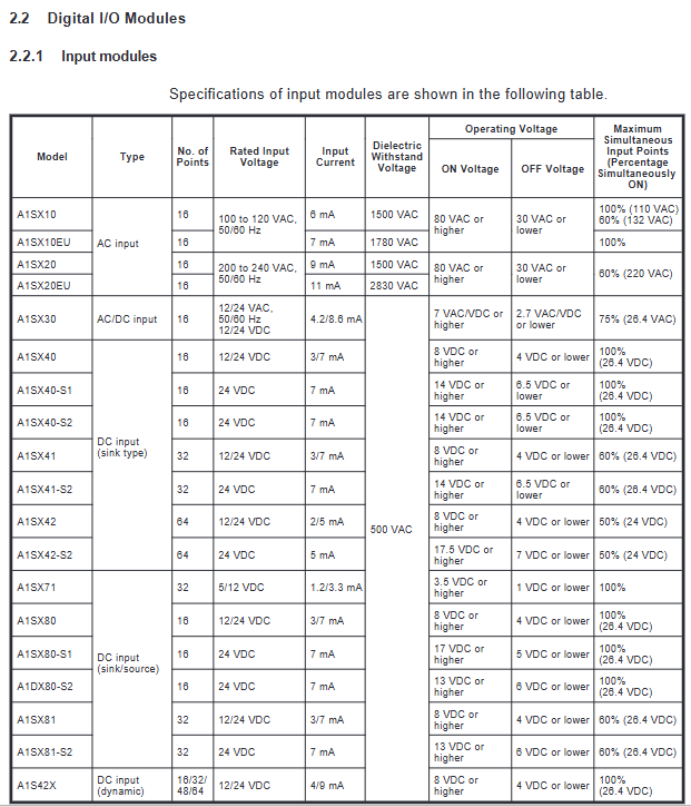
2. Input module (classification)
AC input: A1SX10EU (200VAC, 16 points)
DC input: A1SX40 series (24VDC, 16/32/64 points)
AC/DC input: A1SX30 (12/24VAC/DC, 16 points)
Key parameters: response time of 0.1~35ms, withstand voltage of 500~2830VAC
3. Output module (classification)
Type, model, load response time
Relay A1SY10 2A/point, 240VAC 10ms → 12ms
Controllable silicon A1SY22 0.6A/point, 200VAC 1ms
Transistor A1SY40 0.1A/point, 24VDC 2ms
4. Hybrid I/O modules
A1SH42:32 in 32 out (DC transistor)
A1SX48Y18: 8 inputs and 8 outputs (relay)
A1SX48Y58: 8 inputs and 8 outputs (transistor)
Installation specifications
Installation environment: It must be installed in a control cabinet with an IP54 or higher rating
EMC requirements
Control cabinet metal material, multi-point grounding
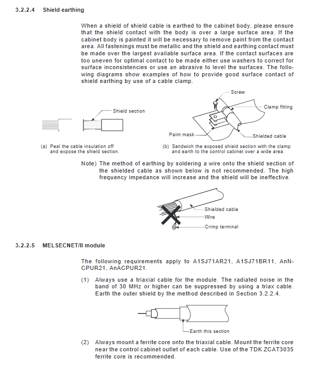
Shielded wire with large area grounding, cable with magnetic ring added
Separation of power and signal lines
Module installation
The bottom buckle is securely fastened to the base
Up and down spacing * * ≥ 30mm * *, both sides * * ≥ 50mm**
DIN rail: TH35-7.5, screw spacing ≤ 200mm
grounding
LG/FG use * * ≥ 2mm ² * * wire for short distance grounding
Large area connection of shielding layer to cabinet
Wiring specifications
Power wiring
First connect the PLC power supply, then connect the load power supply
It is prohibited to connect multiple power supplies in parallel to supply power to the same module
I/O wiring
Input: DC 24V, COM common terminal
Output: Relays can be AC/DC, transistors only DC
Wire diameter: 0.75~1.25mm ², torque 59~88N · cm
communication wiring
RS-232C: Cable ≤ 15m
Shielded wire single ended grounding to reduce interference
Fault safety design
mandatory requirement
External emergency stop, limit, forward and reverse interlock
Key outputs are monitored separately
Output circuit with fuse
power-up sequence
Power supply for PLC
Supply power to the load
start operation
Program driver output
Maintenance and upkeep
1. Daily inspection
The base, module, and wiring are not loose
POWER/RUN/ERROR indicator lights are normal
Input/output LED status is normal
2. Regular inspection (6-12 months)
Environmental temperature and humidity, non corrosive gases
Power supply voltage, terminal fastening, dust prevention
Battery status (M9006/M9007)
3. Battery replacement
Battery model: A6BAT
Low voltage alarm: M9006/M9007 action
Replacement requires power-off operation
Error code (core)
Error code, error name, reason handling
10 instruction code error program including unable to decode instruction correction program
11 Parameter Error Parameter Area Damaged Reset Parameters
22 WDT Error Scan Timeout Optimization Program
Unit 31 verification error module plug-in/model mismatch reinstallation
32 fuse blown, output short circuit replaced fuse
70 battery error, low voltage/disconnection, replace A6BAT
Appendix Core
CPU difference
A1SHCPU: speed 0.33 μ s, 2048 I/O points, supports CC Link
A2SHCPU: Speed 0.25 μ s, Memory 64KB
A2ASCPU: speed 0.15~0.20m/step, memory 256KB
CE compatible module
CPU:A1SH/A2SH
Power supply: A1S61PEU/62PN
I/O: A1SX10EU, A1SY10EU, etc
CC Link specific instructions: RLPA/RRPA/RIRD/RIWT, totaling 11
Key issues
Question: What external circuits must be included in the fail safe design of MELSEC-A series PLCs? What are the mandatory requirements for the power on sequence?
Answer: It must include emergency stop circuit, limit position protection, forward and reverse interlock, and critical output monitoring circuit; The strict power on sequence is: ① supplying power to the PLC host → ② supplying power to external loads → ③ starting the operation switch → ④ driving the output device by the program to prevent erroneous output.
Question: What are the three types of input/output modules for A-series PLC? What are the typical models, maximum load, and response speed of each?
Answer: The three types are: ① Relay output (A1SY10, 2A/point, 240VAC, 10 → 12ms); ② Controllable silicon output (A1SY22, 0.6A/point, 200VAC, 1ms); ③ Transistor output (A1SY40, 0.1A/point, 24VDC, 2ms).
Question: How to determine the battery alarm of A-series PLC? What are the replacement requirements? What are the items included in daily and regular inspections?
Answer: The low voltage of the battery is indicated by the M9006/M9007 alarm; A6BAT must be used, power off for replacement. Daily inspection: module fixation, wiring, LED status; Regular inspection (June to December): environmental temperature and humidity, power supply voltage, terminal torque, battery status, dust and corrosion prevention.