Mitsubishi MELSEC AnS (H) series CPUs
Positioning and Applicable Scope
The Mitsubishi MELSEC AnS (H) CPU User Manual covers A1SHCPU, A2SHCPU, A2SHCPU S1, A1SJHCPU, and is equipped with A1S61PN/A1S62PN wide range power modules. It is a complete guide for the design, installation, wiring, debugging, maintenance, and troubleshooting of AnS series compact PLCs.
Safety precautions (mandatory grading)
DANGER: It is necessary to establish external emergency stop, limit, and interlock safety circuits; Power off operation, prohibit touching terminals with electricity on; The battery is prohibited from charging/heating/short circuiting.
CAUTION: The distance between the control line and the power line is ≥ 100mm; the terminals are tightened according to the specified torque; Prohibition of modification and disassembly; Dispose of waste as industrial waste.
System configuration architecture
scalability
Maximum expansion level: 3 levels
I/O points: A1SH=256, A2SH=512, A2SH-S1=1024 points
Support base: Main base A1S32B/33B/35B/38B; Expansion base A1S52B/55B/58B (S1)
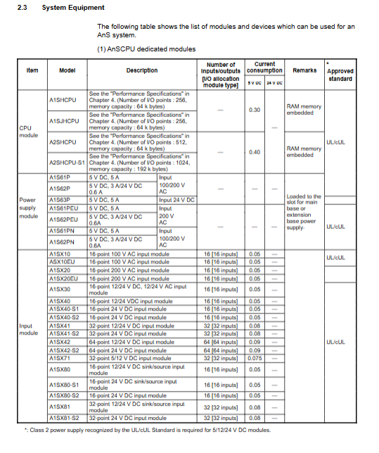
Compatible module
Digital I/O, analog, temperature, high-speed counting, positioning CC‑Link、 Ethernet, computer link module
Peripherals: GPP programmer, A6WU ROM writer, A7PU/A8PUE programming unit
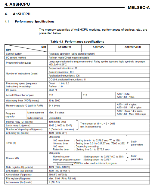
Core Performance Parameters
Project A1SHCPU A2SHCPU A2SHCPU S1
Instruction processing speed 0.33 μ s 0.25 μ s 0.25 μ s
Program capacity: 8k steps, 14k steps, 30k steps
Maximum I/O points 256 512 1024
Built in RAM 64kB 64kB 192kB
File register R has a maximum of 8192 points and a maximum of 8192 points
Watchdog WDT 10-2000ms 10-2000ms 10-2000ms 10-2000ms
Clock function support
Battery backup A6BAT (5 years) A6BAT (5 years) A6BAT (5 years)
Power module A1S61PN
Input: 100-240VAC wide range
Output: 5VDC/5A
Allow instantaneous power outage: ≤ 20ms
Certification: UL/cUL/CE
CPU core functions
Operation mode: RUN/STOP/PANSE; PAUSE can maintain the output state.
Power down hold (Latch): L/B/T/C/D/W data battery backup, supports Latch Clear clearing.
I/O control: Direct mode/Refresh mode can be switched.
Advanced features
Constant scan: 10-2000ms fixed scan
State Lock (SLT): Save all device states in case of failure
Sampling Tracking (STRA): Timing sampling equipment changes for debugging purposes
Offline switch: Forcefully disconnect output during operation for testing purposes
Error LED priority: can block low priority error lights from turning on
Installation and wiring specifications
Install
Method: DIN rail TH35-7.5 or wall mounted
Spacing: ≥ 30mm on all sides; ≥ 80mm on top (expansion base)
Environment: 0-55 ℃, 10-90% RH, no pollution/corrosion
wiring
Power off operation; FG/LG must protect grounding
Strong and weak current separation ≥ 100mm
Shielded cables are used for analog/communication lines, with a single end grounded
EMC and Low Voltage Directive Compliance
EMC: Compliant with EN50081-2/preEN50082-2
Measures: Control cabinet grounding, shielded cable, magnetic ring, power filter, strong and weak current separation
Low voltage command: compliant with EN61010-1; Use reinforced insulation power supply/IO modules; Installed inside a lockable control cabinet
Maintenance and Inspection
Daily inspection: LED status, terminal fastening, module fixation, environmental dust
Regular inspection (6-12 months): voltage, temperature, battery, grounding, connectors
Battery replacement
Lifespan: 5 years
Complete the replacement within 5 minutes after power failure to avoid program loss
Fault diagnosis (core fault code)
10: Instruction code error → Program illegal instruction
11: Parameter Error → Parameter Damage/Memory Card Exception
20: RAM error → CPU hardware failure
22: WDT error → scan timeout, dead loop
31: Module comparison error → Module insertion/model mismatch
32: Fuse blown → Output overload/short circuit
40: Control bus error → Special module/base failure
70: Battery error → low voltage/not connected
Key questions and answers
Question 1: What are the core differences between the three operation modes (RUN/STOP/PANSE) of AnS (H) CPU?
answer:
RUN: Execute the program normally and output actions that follow the program.
STOP: Stop the program, all outputs (Y) are closed, and data remains except for the output.
PAUSE: Stop the program but maintain all current output states, used in pause scenarios where output interruption is not allowed.
Question 2: What are the advantages of the A1S61PN power module? Why do we need to verify the terminal voltage when expanding the system?
answer:
Advantages: 100-240VAC global wide voltage input, no switching required, compatible with global power grids; Instantaneous power outage can withstand 20ms, making the system more stable.
The expansion base is powered by the main power supply through an extension line, and there is a voltage drop in the cables; Require the terminal voltage to be ≥ 4.75VDC, otherwise it may cause module misoperation or crash.
Question 3: What is the reason for the WDT watchdog error (code 22/25)? How to quickly solve it?
answer:
Reason: The program scanning time exceeds the WDT set value (default 200ms), which is often caused by dead loops, excessive instructions, long interrupts, and instantaneous power outages.
solve:
Check for END dead loop
Inserting WDT instruction to reset timer in long program
Increase WDT setting value (maximum 2000ms)
Optimize the program and split long scans