OMRON SYSMAC NX series NX1P2 CPU unit
Core positioning
Product: NX1P2 series integrated machine automation controller
Version: W578-E1-14
Purpose: Integrated sequence control and motion control, small modular, high reliability, EtherCAT/EtherNet/IP dual network native
Applicable: Small equipment, production lines, handling, packaging, machine tools, electronic manufacturing and other automation equipment
Product Overview and Core Features
1. Core positioning
Small integrated controller: CPU+built-in I/O+dual network ports+expansion slots, no additional rack required.
2. Key highlights
Built in EtherCAT master station (up to 16 slaves)
Built in EtherNet/IP (100Mbps)
Built in I/O: 14~40 points, NPN/PNP optional
Scalability: Up to 8 NX modules+1-2 optional boards
Battery free operation: Programs, data retention, and event logs are all stored in non-volatile memory
SD card: backup/restore/automatic program distribution
Compliant with safety concept: External emergency stop, interlock, and safety circuit must be externally installed
3. Model classification (by number of axes and I/O)
NX1P2-1140DT/DT1:12 axis, 40 point I/O (24 in/16 out)
NX1P2-1040DT/DT1:10 axis, 40 point I/O
NX1P2-9024DT/DT1:4 axis, 24 point I/O (14 in/10 out)
NX1P2-9BxxxxDT/DT1:2 axis, simplified version
System architecture
1. Basic components
NX1P2 CPU Unit
NX I/O modules (up to 8)
End cap NX-END02
Optional boards: serial port, analog I/O
SD card
Battery (optional, only for long-term clock maintenance)
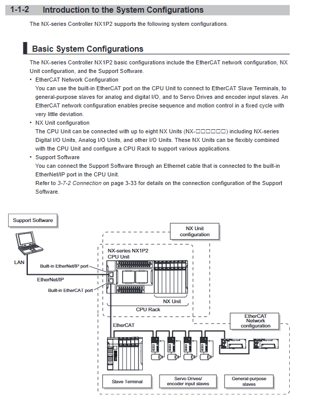
2. Network architecture
EtherCAT: Motion, Remote I/O, Servo, Inverter, Vision
EtherNet/IP: upper computer, HMI, PLC interconnection, IT access
Serial port (optional): RS232/485, Modbus RTU, no protocol
3. Software platform
Sysmac Studio: Unified Programming, Configuration, Debugging, and Simulation
Follow IEC 61131-3+PLCopen motion control
Hardware Structure and Interface
1. Front panel components
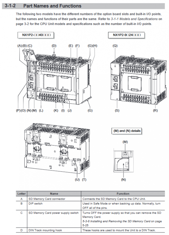
SD card slot+power switch
DIP switch: safe mode, backup, restore, automatic transfer
Status lights: POWER/RUN/ERROR/BUSY/SD PWR/SD BUSY
Dual Ethernet ports: PORT1=EtherNet/IP, PORT2=EtherCAT
Removable terminal block: power supply, grounding, built-in I/O
Optional board slots (1-2)
battery compartment
2. Terminal definition (emphasis)
Power supply: 24VDC ± 10%
Grounding: Functional grounding (must be connected)
Input: 24V universal, high-speed/normal separated
Output: NPN/PNP transistor, 300mA per point
Public end: segmented and independent to enhance anti-interference capability
3. Optional board
NX1W-CIF01:RS232
NX1W-CIF11/12: RS485 (non isolated/isolated)
NX1W-ADB21:2 analog input
NX1W-DAB21V: 2-channel analog output
NX1W-MAB221:2 input 2 output analog quantity
Power System Design (Core Chapter)
1. Two completely independent power sources
Unit power supply: provides power to the CPU, modules, and circuits
I/O power supply: provides power to input/output, sensors, and loads
Power supply must be separated and not shared to prevent noise interference.
2. Power supply restrictions
CPU provides NX module power supply: maximum 10W
I/O power bus current: maximum 4A
NX power auxiliary unit must be added if exceeded
3. Selection of protective devices
Input terminal circuit breaker/fuse: selected based on impulse current+rated current
The power supply must meet SELV and double insulation requirements
4. Voltage drop calculation
Voltage drop per unit connection: 0.02V~0.08V (by current)
It is necessary to ensure that the terminal load voltage is within the specifications
Installation and wiring specifications
1. Installation environment
Temperature: 0~55 ℃
Dustproof, corrosion-resistant, and vibration resistant
It must be installed vertically to ensure the air duct
Stay away from strong electricity and interference sources ≥ 200mm
2. Installation method
DIN rail installation (35mm)
Cannot be installed sideways/upside down
Module splicing: Yellow slider pushed to the bottom with a “click” lock
3. Key points of wiring
Turn off the power first and then connect the wires
Communication cables with double shielding of Category 5e or above
EtherCAT and power line separation wiring
CT strictly prohibits open circuit
Shielding layer single ended grounding
4. Safety grounding
Functional grounding ≤ 100 Ω
Separate strong grounding from weak grounding
Safety precautions (mandatory requirement)
1. Absolutely prohibited
Touch the terminal when powered on
Power on disassembly module
Reverse connection of power supply and I/O
Connect the output terminal to the power supply
2. The safety circuit must be external
Emergency stop, limit, interlock, and safety door must be implemented in external hardware
Prohibit relying solely on program security
3. Failure safety design
When the CPU fails, loses power, or experiences communication abnormalities, all outputs are safely shut down
Risk of transistor breakdown in output: Hardware relay for ultimate cut-off
Status lights and diagnostics
1. Core Lamp Meaning
POWER green: Power supply is normal
RUN Green: Running
ERROR red: Fault (constantly on=major fault, flashing=minor fault)
BUSY flashing yellow: Reading and writing internal storage
SD light: SD card access in progress
2. Network lights
NET RUN: Network is normal
NET ERR: Network failure
Link/ACT: Link/Data Activity
Backup and Recovery (DIP Switch)
Pin1=ON: Safe Mode (program not running)
Pin2=ON: Backup to SD
Pin3=ON: Restore from SD
Pin4=ON: Automatic transmission upon startup
Modify DIP and power it back on to take effect.
Battery usage
Default without battery
No battery: The clock is held by a capacitor (approximately 10 days/40 ℃)
Long term clock maintenance required: installation of CJ1W-BAT01
Maintenance and upkeep
Regular inspection: Terminal fastening, heat dissipation, dust, cable damage
Fans and capacitors are vulnerable parts
The insulation test must be conducted after disconnecting the power and wiring
SD card cannot be plugged in or unplugged with power on (power off switch must be pressed first)
Principles of fault handling
Viewing lights: POWER/RUN/ERROR
Check power supply: 24V, grounding, wiring
Check network: EtherCAT/EtherNet/IP link
Check I/O: input power supply, output load, short circuit
Clear errors, reset, and power on again
Viewing event logs using Sysmac Studio