ABB ACS550 frequency converter
Basic information of the document
Model range: ACS550-01 (IEC)/ACS550-U1 (NEMA)
Power: 0.75… 160 kW/1… 200 hp
Voltage: 208~240V, 380~480V, 500~600V
Firmware version: V3.14e and above
Applicable motor: three-phase asynchronous motor
Core applications: fans, water pumps, conveyor belts, compressors, general mechanical speed regulation
Core security standards (mandatory compliance)
Must be installed by a professional electrician
Wait for 5 minutes after power failure to ensure that the DC bus is fully discharged
Do not connect the power supply to the output terminal U/V/W
IT systems and corner grounded TN systems must remove internal EMC filters
Do not install capacitors or surge absorbers on the output side
Emergency stop must be achieved through external hardware circuits
Installation and environmental requirements
Installation direction: Must be installed vertically
Temperature: -10…+40 ℃ (installed side by side without gaps)
Protection level: IP21/UL Type 1; IP54/UL Type 12 (optional)
Spacing: Up and down ≥ 100mm, left and right ≥ 10mm
Altitude: ≤ 1000m without capacity reduction, higher altitude requires capacity reduction
Framework: There are 6 sizes of R1~R6, corresponding to different powers
Wiring (Core Chapter)
1. Main circuit terminal
Input: U1/V1/W1 (three-phase), single-phase connected to U1/W1
Output: U2/V2/W2 → Motor
Braking: R1-R2 use BRK+/BRK -; R3-R6 using UDC+/UDC-
Grounding: PE must be reliably grounded
2. Control terminal (X1)
AI1/AI2: 0~10V/0~20mA (DIP switch switching)
DI1~DI6: Digital inputs (start, stop, direction, multi-stage speed)
RO1~RO3: Relay output (ready, running, faulty)
AO1/AO2: 0~20mA analog output (frequency, current)
+24V/GND: Panel auxiliary power supply
3. Wiring rules
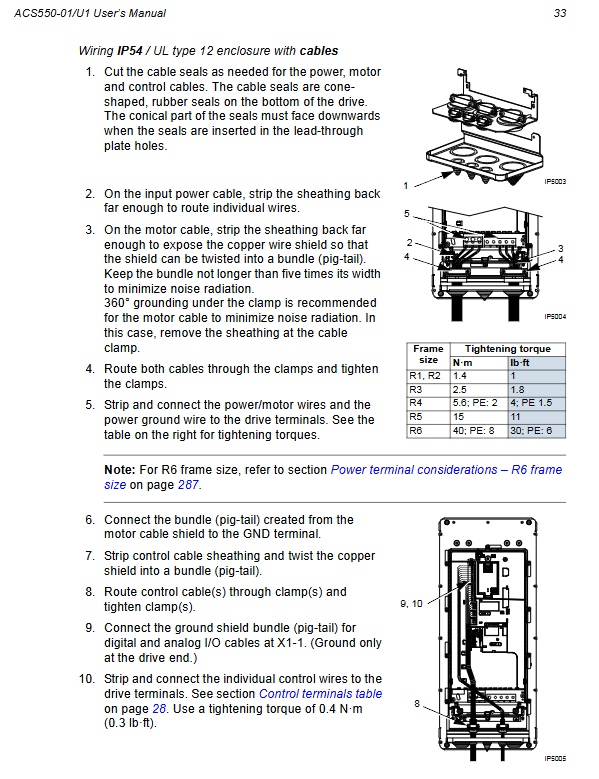
Separate the wiring of the main circuit and control lines
Single end grounding of motor wire shielding layer
CT current circuit must not be open circuited
The maximum length of the cable is 50m, and if it is too long, an output filter needs to be added
Control panel operation
Two types of panels
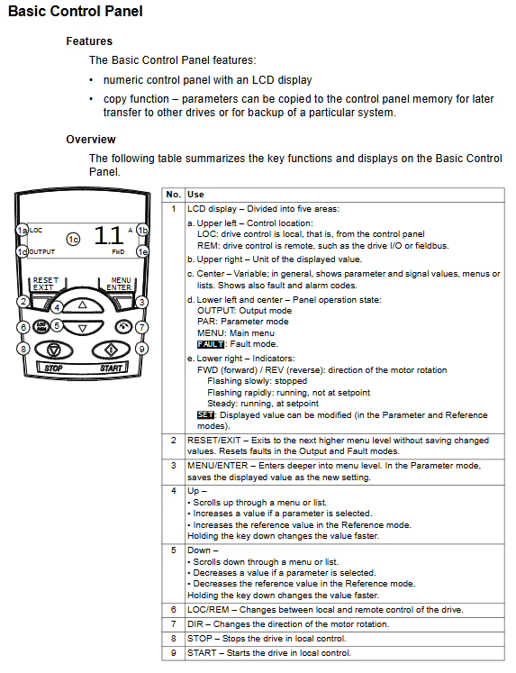
Basic Control Panel
Buttons: START/STOP, LOC/REM, ▲/▼ RESET
Mode: Output Display, Parameters, Reference Values, Copy, Fault
Assistant Control Panel
With guide, multiple languages, help, parameter backup, clock
Provide a startup wizard to complete debugging with just one click
Core Operations
LOC/REM: Local/Remote Switching
START/STOP: Local start stop
DIR: Direction Switching
RESET: Fault reset
Start Debugging (ID Run and Quick Start)
1. Quick start steps
Input motor nameplate parameters (99 sets)
Select control mode: Vector/V/F
Execute ID Run (required for vector control)
Set acceleration and deceleration time
Check the steering and conduct a trial run
2. ID Run (motor identification)
Function: Accurately measure motor parameters and improve vector control performance
Condition: No load on the motor, disconnected from the load
Setting: 9910=1 (ON), start automatic execution
Application macros (one click configuration of I/O)
Macros are pre-defined parameter groups that can quickly adapt to different scenarios
ABB Standard: default 2-wire control
3-Wire: Control with a jog button
Alternate: Forward and Reverse Alternating Logic
Motor Potentiometer: Digital Speed Adjustment
Hand/Auto: Commonly used for HVAC
PID Control (PID Macro): Constant Voltage/Constant Current/Constant Temperature
PFC Control (Multi Pump Macro): Pump group rotation control
Torque Control: Tension Control
Parameter system (complete grouping)
Key parameter group
99 sets: startup parameters (motor nameplate, control mode)
Group 01: Operating data (current, frequency, torque, temperature)
10 groups: start stop/direction
Group 11: Frequency Source Selection
12 groups: multi-stage speed
13 groups: Analog input
14 groups: Relay output
15 sets: Analog output
20 groups: Limiting (current, torque, speed)
Group 21: Start stop function (DC braking, excitation)
Group 22: Acceleration and Deceleration
30 sets: Fault protection
40 sets: PID control
52 groups: Panel communication
81 groups: PFC multi pump control
Control mode
Scalar (V/F): Universal, multi motor, simple occasion
Vector: Speed: High precision, large low-speed torque
Vector: Torque: Tension, winding
Protection function
Overcurrent (OC), Overvoltage (OV), Undervoltage (LU)
Overload (OL), Overheating (OH), Earth Fault
Motor overheating, external malfunction, communication failure
Support automatic reset (31 groups)
Fault diagnosis
Common fault codes
1: Overcurrent
2: DC overvoltage
3: Overheating of heat sink
4: Output short circuit
5: DC undervoltage
6: AI1 lost
7: AI2 lost
8: Motor overload
10: Panel communication lost
11: ID Run failed
16: Blocked rotation
21: External malfunction
Investigation process
View fault records (Group 04)
Check the wiring and motor insulation
Check parameters and acceleration/deceleration time
Check the load and mechanical blockage
Reset and power on again
Maintenance and upkeep
Daily: Check temperature, noise, vibration, and fan
Regular: tighten terminals, clean air ducts, check fans
Vulnerable parts: cooling fan, electrolytic capacitor
Insulation test: must be conducted after disconnecting the wires and cutting off the power
Communication function
Built in RS485: Modbus RTU
Optional adapters: Profibus DP, DeviceNet, CANopen, EtherCAT, Ethernet
Parameters: Station number, baud rate, parity check (52 groups, 53 groups)
Typical application configuration
Panel control: AI1 potentiometer, DI1 start stop
Multi speed: DI3/DI4 switch to 3-speed
PID constant pressure water supply: AI2 pressure feedback, PID macro
Multi pump rotation: PFC macro, automatic pump addition/reduction
Torque control: AI2 torque given, torque macro
Modbus monitoring: RS485 reads current, frequency, and faults