Allen Bradley Classic 1785 PLC-5 Series Programmable Logic Controller
Chapter 1 System Cognition
Explain centralized control/distributed control architecture
Define key terms: local I/O, remote I/O, discrete transfer, block transfer
The processor can operate in two modes:
Scanner mode: Proactively manage remote I/O
Adapter mode: Managed by the higher-level controller as a slave station
Provide a functional specification development process to guide project design
Chapter 2 Hardware Selection
Hardware selection covering the entire system:
I/O modules: selection rules for discrete, analog, and intelligent modules
Adapter Module: 1771 ASB/ALX Remote I/O Adapter
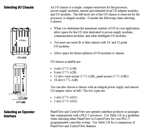
Rack: 4/8/12/16 slots 1771 series
Processor: PLC-5/10/12/15/25 Performance Comparison
Power supply: Backplane current calculation, selection of internal and external power supplies
Memory: EEPROM/CMOS memory module (1785 MJ/MK/MS/MR)
Battery: 1770-XY lithium battery, with a lifespan of approximately 2 years
Complementary I/O: Redundant configuration of master-slave rack pairing
Redundant system: 1785-BCM backup module forms a dual machine hot backup
Cable and Terminal: DH+, Remote I/O Link Terminal and Wiring
Chapter 3 Hardware Layout and Installation
Environmental requirements: 0~60 ℃, humidity 5~95%, no condensation
Cooling distance: Leave 6 inches on the top and bottom of the rack, and 4 inches on the left and right
Anti static: Anti static wristbands must be worn when inserting and removing modules
Wiring specifications: separation of strong and weak electricity, shielding grounding, cable tray planning
Grounding: Remote I/O system recommends star grounding
Chassis size and mounting hole spacing: standard 19 inch installation
Chapter 4 Address Mode, Rack and Group Allocation
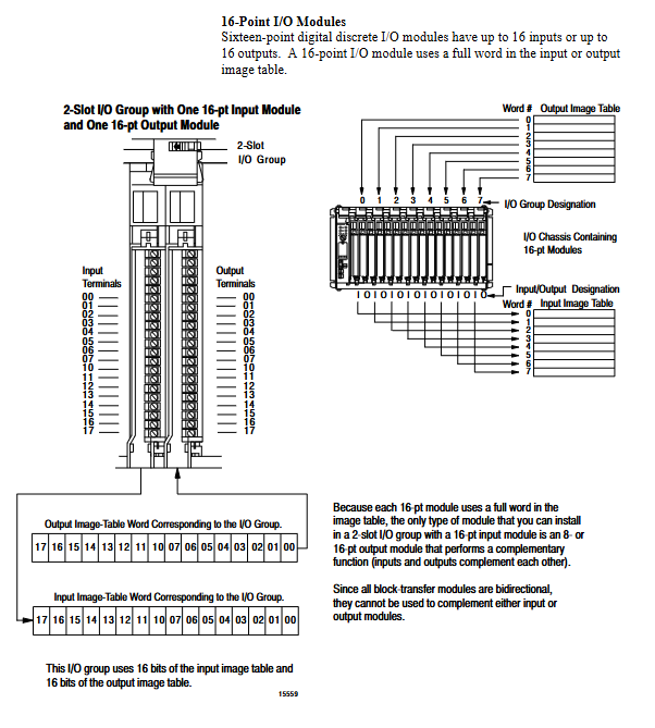
Supports three types of I/O addressing methods:
2 slots: 2 slots=1 group
1 slot: 1 slot=1 group
1/2 slot: 1 slot=2 groups (high-density dedicated)
Rule:
1 rack=8 groups
Local rack default address 0
Remote rack can be allocated across chassis
Complementary I/O configuration: primary/backup rack address mapping to achieve redundant I/O
Chapter 5 Communication Configuration
Processor interfaces: DH+, Remote I/O, serial port
DH+Network:
Up to 64 stations
Speed 57.6kbps
Chrysanthemum chain/mainline branch topology
Remote I/O:
Speed 57.6k/115.2k/230.4kbps
Distance decreases with speed
Programmer connection method:
Directly connected to DH+
Remote (DH+→ DH)
Serial port (1785-KE/1770-KF2)
Switch SW1/SW2 configuration scan/adapter mode, station number, rack number
Chapter 6 System Program Planning
Support mixed programming of SFC sequential function diagram and ladder diagram
Data table file structure:
I/O image, bit file, timer, counter, integer, floating point
Addressing format:
Logical address, indirect address, index address, symbolic address
Processor status file S2: Monitoring scan time, faults, DH+station number, I/O status
Chapter 7 Interrupt Program Selection
Supports four types of interrupts:
Fault Routine: Execute in case of major faults
Power on program: Startup initialization
Timer Interrupt STI: Periodic Execution
Input Interrupt PII: Signal Triggered
Classification of major faults: recoverable/non recoverable
Fault codes and handling: program errors, memory errors, addressing errors, I/O faults
Power on protection: Power off restart does not automatically enter operation mode
Chapter 8 Discrete and Block Data Transmission
Adapter mode (slave)
Discrete transmission: automatic exchange of data with the main station
Block transmission BTR/BTW: up to 64 words, initiated by the master station and responded by the slave station
Adapter Image File: Custom Data Area Replacement Rack 3
Scanner mode (main station)
Local I/O: synchronous scanning
Remote I/O: Asynchronous scanning
Block transfer queue: up to 17 requests per rack
Priority execution of block transfer in fault program
Chapter 9: Program Timing Calculation
Scan cycle=logical scan+internal processing
Factors affecting scanning time:
Instruction type (contact/instruction/file instruction)
True or False Conditions
indirect addressing
Data location (front 4K/back 4K)
Provide a complete instruction execution schedule (microsecond level)
Chapter 10 System Performance Optimization
Throughput: Total delay from input change to output action
Optimization methods:
Increase communication speed (230.4kbps)
Key I/O independent channels
Optimize scanning list (high-frequency rack multi scan)
Block transmission dispersed to different racks
Reduce unnecessary block transfers
Switch settings (core engineering parameters)
Chassis backplane switch: addressing mode, output hold, EEPROM loading
1771 ASB adapter switch: rack number, baud rate, group start address
Processor SW1: DH+station number, scan/adapter mode
Processor SW2: Adapter mode rack number, word length, group address
SW3: DH+/Remote I/O Link Terminal