Siemens SIMOVERT MASTERDRIVES Vector Control (VC) Inverter Operating Instructions
Basic Information
Applicable products: SIMOVERT MASTERDRIVES VC vector control frequency converter (6SE70 full series)
Core applications: Wiring, operation, parameter setting, debugging, control, and fault diagnosis of frequency converters
Language: English (simultaneous release of German, French, Spanish, and Italian versions)
Overview of core content
0 General and Security
Define professional personnel, danger/warning/caution levels
Mandatory requirements for ESD anti-static operation
Low voltage instruction, EMC installation specifications
Applicable standards: EN 50178, VDE 0160, etc
1. Control terminal and serial interface
Control board CU terminal definition: X100/X101/X102/X103
X100:RS485、 relay output
X101: 7-way digital input, 24V power supply
X102: 2-channel analog input, 1-channel analog output
X103: Encoder interface, motor temperature, analog output 2
PMU operation panel interface X300 (RS232/RS485)
EMC shielding, grounding, and wiring specifications
2 Operation and Display
PMU panel buttons: ON, OFF, steering, P key, lift key
Display structure: Parameter number → Index → Parameter value
Fault/alarm display, numerical shift, quick switching operation
Operation hierarchy and menu logic
3 Terminology and Functional Scope
Control type: V/f, vector frequency/speed/torque control
Process data: control words, status words, set values, actual values
Index parameters, dataset (SDS set values/MDS motor dataset)
Basic/Reserve Switching (Manual/Automatic)
4. Start Debugging (Core)
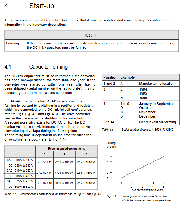
Capacitor activation: must be executed if shutdown exceeds 1 year
First boot
Standard applications: language, access level, motor nameplate, V/f parameters
Expert applications: vector control, encoder, option board
P052 Function Selection (Key)
1=Factory reset
2=Initialization (change model)
4=Hardware configuration (CB/TB/SCB/TSY)
5=Driver settings
6=Automatic parameterization
7=Static motor identification
8=Complete motor identification
9=No load measurement
10=Speed loop optimization
12=Encoder Test
Control logic and timing of external main contactor
5 Process Data (Control/Status/Setting/Actual)
Control word 1/2 (r550/r551): start stop, steering, reset, jog, dataset switching
Status word 1/2 (r552/r553): Ready, Running, Fault, Alarm, Frequency Arrived
Set value channel: main setting, additional setting, fixed setting, motor potentiometer
Actual values: speed, current, voltage, torque, temperature
Source selection: Terminal PMU、 Serial port, option board
6 interfaces
Digital input (7 channels): start stop, reset, direction, external fault
Digital output (4 channels): running, faulty, ready
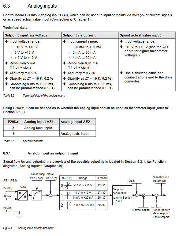
Analog input (2 channels): 0-10V/0/4-20mA, wire breakage detection
Analog output (2 channels): 0-10V, output actual value
Serial interface: SST1/SST2 (USS), DPR dual port RAM
Slope generator RFG: acceleration and deceleration, current limiting, inflection point smoothing, resonance suppression
7 open-loop/closed-loop control
V/f control: linear/parabolic, torque boost, excitation attenuation, IxR compensation
Vector control:
No sensing vector (P163=3)
Encoder speed vector (P163=4)
Torque vector (P163=5)
8 Startup Function (P052 Detailed Explanation)
Factory settings, initialization, download, hardware configuration, driver settings
Automatic parameterization, static/complete motor identification, no-load measurement, speed loop optimization, self check, encoder testing
Provide a complete model PWE comparison table (6SE7014-6SE7045)
9 Software Functions
WEA: Automatic restart during power outage
KIP: Kinetic energy buffering (does not slow down during short-term power outages)
FLN: Flexible response (low voltage without capacity reduction)
Vdmax control: DC bus overvoltage suppression
DC braking: quick parking
Speed start: restart while spinning
Process controller: Built in PID (pressure/flow/liquid level)
Tracer: 8-channel oscilloscope function
Temperature adaptation: Resistance compensates with temperature to improve accuracy
10 Function Diagram
Complete schematic diagram of analog quantity, set value channel, slope, control circuit, and I/O mapping
Engineering grade signal flow for deep debugging
11 Parameter Table (Complete)
Observation parameters, general parameters, driving data, hardware configuration, motor data
Control, function, set channel, control/status word, analog I/O, communication, diagnosis, modulator
12 Faults and alarms
Fault code Fxxx: overcurrent, overvoltage, undervoltage, overheating, grounding, short circuit, communication
Alarm code Axxx: Overload, preheating, resonance, stall
Fault value r947/r949 locating the cause
13 logs and 14 indexes
Fault log recording and abbreviation list
Key points of core technology
Control method
V/f: Universal for fans and pumps
Vector: high-precision speed/torque control
key parameters
P051: Access level (2 standards/3 experts)
P052: Start debugging function
P100~P109: Motor nameplate
P163: Control mode
P462/P464: Acceleration and deceleration time
P554~P591: Control word source
P650/P655: Analog I/O configuration
protection function
Overcurrent, overvoltage/undervoltage I²T、 Motor overheating, grounding, short circuit
Advanced features
Speed start, kinetic energy buffering, automatic restart, built-in PID, dataset switching
Debugging process
Factory reset → Hardware configuration → Motor parameters → Automatic parameterization → Motor identification → Control settings → Trial operation