JUMO dTRANS p35 Pressure Sensor Operation Manual with IO Link Interface
Basic Introduction and Safety Notice
1. Product Usage
This sensor is used for measuring and monitoring the gauge pressure and absolute pressure of liquids and gases, with built-in signal amplification and digital processing circuits; Equipped with IO Link 1.1 bidirectional communication interface, it can transmit process data, parameters, diagnostics, and status information, adapt to factory and mechanical automation systems, and is only allowed for indoor use.
2. Safety signs and warnings
CAUTION: Failure to operate as required can result in equipment damage and data loss.
Refer to document identification: The equipment documentation must be read to identify risks and take necessary precautions.
NOTE: Indicate key instructions for product usage and operation.
REFERENCE: Guide to refer to other chapters/accompanying manuals in the document.
3. Environmental and Media Risk Warning
High temperature surface: Measuring high-temperature media can cause the equipment casing to become hot, requiring shutdown for cooling, wearing protective equipment, or installing protective devices.
Hazardous media: Before coming into contact with corrosive or abrasive hazardous media, a risk assessment should be conducted in conjunction with the material safety data sheet to prevent leakage, fire, and personal injury.
4. Core usage restrictions
It does not belong to the safety accessories of pressure equipment and cannot be used for safety critical working conditions;
Prohibit installation and use in explosion-proof areas;
Equipment equipotential system needs to be connected through process interface.
5. Qualification requirements
Equipment installation, wiring, and debugging must be completed by qualified professionals.
Certification, Appearance, and Model Identification
1. Authoritative certification
Having multiple certifications such as UL, EHEDG, H2 ready, and China RoHS, it meets industry standards for food hygiene, hydrogen energy, electrical safety, and more.
2. Equipment structural components
The equipment consists of a status LED, a pressure interface with a diaphragm, an M12 electrical interface, and a transport protective cap; After power on, the dual green LEDs remain on, and after establishing an IO Link connection, the LEDs turn to flashing.
3. Nameplate information
The nameplate indicates the equipment name, order number, measurement range, power supply parameters, output type Device ID、 Production number; The production number can interpret the year and week of manufacture, and the Device ID is used to search for the matching IODD device description file.
4. Ordering coding rules
The complete order code is divided into 8 segments, defining the basic model, expansion type, measurement range, output form, pressure interface, interface material, electrical interface, and additional options:
Basic model: 402058 (dTRANS p35 IO Link pressure sensor);
Expansion types: regular, temperature resistant, customized versions;
Measurement input: Multiple gauge pressure/absolute pressure ranges are available for selection;
Output: Standard IO Link+digital switch output;
Pressure interface: including G-thread NPT、 Various specifications of sanitary clamps, dairy pipeline interfaces, PEKA sanitary interfaces, etc., with different interfaces corresponding to maximum pressure limits;
Interface material: standard 316L stainless steel;
Electrical interface: M12 × 1 circular plug;
Additional options: UL certification, vibration and moisture resistance, pressure channel throttling, hydrogen energy adaptation, etc.
5. Scope of Supply and Accessories
Standard supply: Sensor body+installation instructions;
Optional accessories: IO Link main station (4/8 channels, USB single channel), various connection cables, IODD files, on-site pre configured services, etc.
Detailed technical parameters
1. Measurement performance
Covering multiple gauge pressure and absolute pressure ranges, clarifying the linearity, full temperature accuracy, long-term stability, overload pressure, and burst pressure of each range; Equipped with range over/under limit detection function, output fixed error code in case of abnormality.
2. Output and switch characteristics
Two working modes:
IO Link mode: 1 IO Link communication output, 1 switch output;
SIO standard IO mode: 2 independent switch outputs.
Switch output: Supports PNP/NPN type, maximum single current of 100mA, voltage drop ≤ 2V, with short circuit, reverse polarity protection, and current limiting;
Functional parameters: Delay can be customized, window function delay is fixed at ± 0.25% of the range; The on-off delay of the switch can be adjusted from 0 to 100 seconds; The response time of the switch output is ≤ 7ms.
3. IO Link interface
Version: V1.1 (backward compatible with V1.0), baud rate COM3 (230.4kBaud);
Cable: unshielded cable with a maximum length of 20m and a minimum cycle time of 2ms;
The supporting IODD file can be downloaded from the manufacturer’s official website or IO Link public platform.
4. Electrical parameters
Power supply: IO Link mode DC 18~32V, SIO mode DC 9.6~32V, nominal DC24V;
Power consumption: standby ≤ 10mA, IO Link operation ≤ 12mA, dual switch output maximum ≤ 250mA;
Electrical protection: Complies with Class III safety voltage requirements, and the circuit meets EN 61010-1 energy limiting specifications.
5. Environmental and mechanical parameters
Temperature: Conventional medium -40~+125 ℃, high temperature version can reach 200 ℃; Environmental temperature -40~+85 ℃;
Protection level: Gauge pressure type IP65, absolute pressure type IP65/IP67;
Mechanical performance: anti vibration and anti impact comply with IEC standards;
Material: The diaphragm/interface is made of 316L stainless steel, the high-pressure version uses 630 stainless steel, and the shell is made of 304 stainless steel;
Weight: Approximately 160g, unlimited installation posture, calibration posture requires the interface to face downwards.
6. Size and installation torque
Distinguish the structural dimensions of conventional, high-pressure, and sanitary types; Clearly specify the maximum installation torque for each pressure interface to avoid damaging the seal and threads.
Installation requirements
Universal installation: Install in any posture, ensure that the sealing ring/retaining ring is in place when tightening, and tighten according to the specified torque; Avoid interface position wear and tear.
EHEDG hygiene application requirements:
Select designated hygiene interfaces and support CIP in-situ cleaning;
No cavity, self draining interface, tank installation requires leveling, ensuring proper cleaning and spraying, and exposed leakage ports.
The pressure interface distinguishes the maximum pressure corresponding to different specifications, and mixing of over range interfaces is prohibited.
Electrical connection
1. M12 pin definition (A code)
Line color pin function
Brown BN 1 power supply L+
White WH 2 switch output 2
Blue BU 3 power supply L-
Black BK 4 IO Link/Switch Output 1
2. Key points of wiring
The equipment must be connected to the system’s equipotential;
The UL certified version needs to be paired with cables of the same level of certification;
Provide typical wiring diagrams for PNP and NPN output types.
Equipment functions
1. Switch output function
Support hysteresis function, window function, and can set switch points, release points, and on/off delay; Distinguish between normally open/normally closed contact modes, and the delay function can filter out instantaneous pressure fluctuations.
2. Fine calibration
Used to correct measurement deviations, it can simultaneously adjust the zero point and slope, and adapt to on-site benchmark measurement values; Support quick entry of calibration upper and lower limit values through the teach function.
3. Teach one click function
Includes quick operations such as zero point calibration, factory reset, reset runtime, reset pressure maximum, etc., covering parameter, calibration, and operation and maintenance data reset.
4. Fault alarm
By using the IO Link event code, process data status bit, and numerical error code triple mechanism to report faults, it is possible to identify issues such as range over/under limit, parameter errors, hardware failures, probe disconnection/short circuit, undervoltage, temperature anomalies, etc., and define numerical error codes corresponding to each type of fault.
Parameter configuration
1. Configuration process
Using IO Link master station and supporting software, import device IODD files, establish connections, and complete parameter configuration, monitoring, and diagnosis.
2. Three major categories of parameters
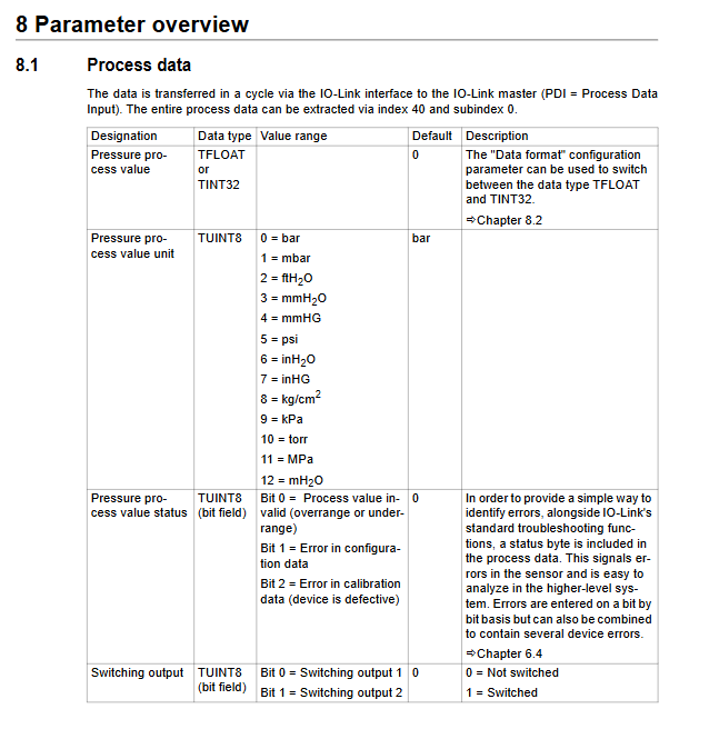
Process data: cyclic transmission of pressure values, data status bits, switch output status; Supports floating-point/integer data format switching.
Configuration parameters: including data format, pressure offset, filtering time, switch output mode, event switch, fine calibration, etc., supporting read and write.
Operation and maintenance service data: read-only runtime, maximum/minimum pressure values; Support command reset statistics data and firmware version viewing; The data is automatically stored in EEPROM every 10 minutes.
Attention: The EEPROM has a write life of about 100000 times, and high-frequency parameter writing is prohibited to avoid memory damage.
Shutdown, scrapping, and compliance
Scrap disposal: Follow the WEEE Electrical Waste Directive, dispose of environmental protection according to local regulations, and contact manufacturers for recycling; Clear the data inside the equipment before scrapping.
Environmental certification: Through China RoHS, the harmful substance content of components such as shells, threads, and pressure interfaces meets the limit requirements.