Beckwith M-3425A Generator Integrated Protection Relay
Product Overview
1. Positioning and core competencies
M-3425A is an integrated generator digital protection system that integrates six functions: protection, measurement, waveform recording, event recording, logic control, and communication. A single device can achieve a complete set of main and backup protection for the generator, supporting single machine and multi machine parallel scenarios, and adapting to generator sets with different grounding and winding structures.
2. Version and Feature Pack Division
The product is divided into basic function package and full function package, and also provides multiple optional extension functions, which can be selected as needed:
Basic package: comes standard with most of the conventional electrical protection, basic logic, and IO functions;
Full function package: includes all the functions of the basic package, and adds advanced protection such as distance protection, step loss protection, and low-frequency accumulation;
Optional functions: synchronous detection (25), rotor grounding/brush detachment protection (64F/64B), low-frequency injection type 100% stator grounding protection (64S), etc. Some optional functions require external hardware.
3. Supporting software, hardware, and options
Supporting modules: M-3925A action indication module, M-3931 human-machine interface (HMI), M-3921 rotor grounding coupler (64F dedicated);
Software tools: S-3400 IPScom (configuration, monitoring, communication), M-3801D IPSlot PLUS (waveform analysis);
Communication accessories: various types of RS-232/RS-485 communication cables, fiber optic components;
Power options: redundant power module (divided into low voltage/high voltage versions);
External hardware (64S dedicated): 20Hz signal generator, bandpass filter, dedicated current transformer.
Complete set of protection functions (numbered according to ANSI standards)
(1) Basic package protection function
24 overexcitation protection (V/Hz): with two characteristics of time limit and inverse time limit, it prevents the generator core from overheating due to low-frequency overexcitation. The parameter range, delay, and reset time can all be set.
27 phase low voltage protection: Three segment fixed value independent configuration, with delay logic, to deal with system voltage loss and fault low voltage.
27TN neutral point third harmonic low voltage protection: relying on the third harmonic to achieve stator grounding auxiliary protection.
32 direction power protection: with three fixed values, it can achieve reverse power, low forward power, and over power protection, used for generator and motor operating conditions, overload protection, and supports sequential tripping logic.
40 demagnetization protection (dual zone offset M-O characteristic): dual impedance area configuration, can stack low voltage acceleration trip logic to prevent generator demagnetization and step loss.
46 Negative sequence overcurrent protection: divided into time limit/inverse time limit, suppresses negative sequence current caused by unbalanced load and phase to phase faults, and prevents rotor overheating.
49 Stator Overload Protection: Based on positive sequence overcurrent, simulate winding thermal accumulation characteristics, set time constant and maximum overload current.
50 phase instantaneous overcurrent, 50N neutral point instantaneous overcurrent: no delay quick break, as the main protection for short circuit.
50DT phase separated differential timed overcurrent: specifically designed for differential protection of split phase windings.
50BF circuit breaker failure protection: After detecting a fault, if the circuit breaker does not open, the failure trip logic will be activated.
50/27 Mis power on protection: Combined with overcurrent and low voltage criteria, it prevents the generator from accidentally closing and being energized during shutdown.
51N neutral point inverse time overcurrent, 51V three-phase inverse time overcurrent with voltage control/lockout: equipped with IEC and IEEE multi class inverse time curves, adapted to different fault characteristics.
59X phase overvoltage, 59N neutral point overvoltage, and 59X multifunctional overvoltage: 59X can be used for inter turn short circuit and bus grounding protection.
59D Third Harmonic Voltage Ratio Protection: Utilizing the third harmonic ratio between the machine terminal and the neutral point to achieve stator grounding protection.
60FL voltage transformer disconnection detection: Identify VT circuit faults, automatically lock relevant voltage protection, and prevent misoperation.
67N residual direction overcurrent: zero sequence direction protection, for grounding faults.
81 frequency protection: four frequency settings, covering high-frequency and low-frequency faults.
87 differential, 87GD ground (zero sequence) differential: Generator main differential protection, distinguishing between phase and ground faults, supporting CT error compensation.
IPSigmic programmable logic: supports AND/OR/non Boolean logic+timer, customizable linkage, lockout, and trip logic.
Circuit Breaker Monitoring (BM) and Trip Circuit Monitoring (TC): Monitor the number of circuit breaker actions and the integrity of the trip circuit.
(2) New protection added to the full-featured package
21. Three stage inter phase distance protection: with M-O impedance characteristics, equipped with load obstacle avoidance barriers and out of step locking, as a backup protection for the line;
78 out of step protection: detect generator and system out of step oscillations, configure impedance circle and sliding pole counting logic;
81A low frequency cumulative protection: divided into 6 frequency intervals, accumulating low frequency operation time to prevent blade resonance damage;
81R Rate of Change in Frequency (ROCOF) Protection: Monitor frequency mutations and respond to islanding and system disturbances.
(3) Optional extended protection
25 Synchronous detection: Verify the voltage, frequency, and phase difference on both sides, support empty line/empty bus logic, and be used for grid locking;
64F rotor grounding protection: To detect grounding faults in the rotor winding, an M-3921 coupler is required, and the injection frequency and grounding resistance can be set to a fixed value;
64B brush detachment protection: monitoring the status of the grounding brush circuit;
64S low-frequency injection type 100% stator grounding protection: external components such as a 20Hz signal source can achieve full range stator grounding protection during unit operation/shutdown.
Hardware, interfaces, and electrical parameters
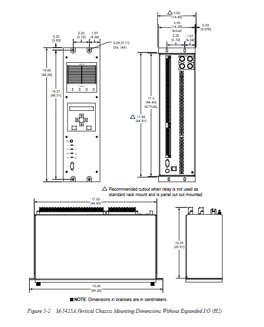
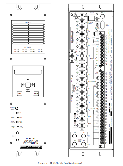
1. Hardware form and installation
Standard 19 inch rack mounted, supporting horizontal/vertical panel installation, divided into standard IO version and extended IO version, with different sizes and weights;
The circuit board is detachable, and the power supply and main circuit are designed to be partitioned;
Working temperature: -20 ℃~+70 ℃, storage, temperature and humidity, vibration, and impact meet industrial relay protection standards.
2. Sampling and Input/Output
(1) Transformer adaptation
CT: Supports two secondary rated currents of 1A/5A;
VT: Suitable for conventional unit voltage transformers, supporting line voltage, phase voltage, and delta/star connection configurations.
(2) Switching quantity
Standard configuration: 6 programmable inputs, 8 programmable outputs;
Expand IO: Add an additional 8 inputs and 15 outputs;
The output contacts meet the ANSI/IEEE C37.90 standard and are capable of self holding/pulse output.
(3) Power system
Main power supply: supports multiple specifications of AC and DC, wide voltage input, and has surge withstand capability;
Optional redundant power supply to enhance power supply reliability;
The tripping circuit and auxiliary circuit voltage support multi-level adaptation.
3. Communication interface (Class III standard+optional network port)
COM1 (Front Panel RS-232): Local PC direct connection, used for on-site debugging;
COM2 (Backplane RS-232): capable of remote communication or IRIG-B timing; After enabling the network port, the communication function is disabled;
COM3 (Backplane RS-485): Two wire bus, supports multi unit network, can connect up to 32 devices at most;
Optional RJ45 Ethernet port: Supports Modbus TCP/IP, BECO2200, IEC 61850 protocols;
IRIG-B time synchronization interface: supports modulation/demodulation signals, achieving millisecond level accurate event timing.
4. Core accuracy and fixed value range
Analog quantities such as current, voltage, frequency, impedance, and power are all given with setting step size, measurement accuracy, and error range;
All protection delays are measured in cycles (1 cycle)= 20ms@50Hz / 16.67ms@60Hz )The maximum setting range is up to 8160 cycles;
Built in multiple sets of inverse time curves: BECO, IEC, IEEE standard curves are fully covered.
Human computer interface and local operation
1. Panel components
M-3931 HMI: 2-line x 24 character backlit display screen+operation buttons, menu style operation;
Status indicator lights: device normal, fault, waveform recording trigger, power supply, circuit breaker position, synchronization status, etc;
M-3925A indicator module: 24 protection action LEDs, 8 output status LEDs, visually display which protection has tripped.
2. Permission management
Set third level access password:
Level 1: Only view parameters, status, and events;
Level 2: Can modify settings and view historical records;
Level 3: Complete configuration, system settings, password modification (highest authority);
Default password disabled, user customizable.
3. Local core functions
Real time monitoring: full electrical parameters such as voltage, current, power, frequency, impedance, harmonics, and third harmonic;
Fixed value viewing/modification, protection of investment and withdrawal;
Query and clear event and trip records;
Manual triggering and viewing of waveform recording;
System time, communication parameters, and device number settings;
Self diagnosis and fault code reading.
Data recording and waveform recording function
1. Event Record (SOE)
Resolution of 1ms, with precise time scale;
Record protection actions, IO displacement, device alarms, communication failures, etc;
Data is not permanently saved in the event of a power outage, resulting in loss. It supports export and printing.
2. Trip target record
Store the last 32 tripping events, record the action protection, current electrical quantity, input/output status, and time scale.
3. Fault recording (oscilloscope function)
Sampling frequency: 16 times the system frequency;
The memory can be divided into 1-16 partitions, with a maximum record length of 416 cycles;
Support pre/post waveform recording, triggering methods: protection action, switch value, communication manual triggering;
File format: COMTRADE, BECO universal format, can be parsed, plotted, and analyzed using IPSplot software;
Wave recording data lost due to power outage.
4. Cumulative quantity monitoring
Accumulated circuit breaker actions and fault current integration;
Accumulated frequency operation (81A dedicated), calculate the total duration of low-frequency operation of the unit.
S-3400 IPScom software operation
This software is a PC core configuration tool that supports multiple connection methods such as serial port, Ethernet, and modem. Its core functions are as follows:
Communication management: Establish connections, set baud rates, addresses, protocols, DHCP/static IP addresses;
Parameter configuration: all protection settings, IO allocation, logic programming, curve setting;
Real time monitoring: primary/secondary electrical quantities, phasor diagram, impedance diagram, out of step/synchronous visualization interface;
File management: parameter upload/download, saving configuration files;
Data analysis: Read SOE, trip records, and waveform files;
Equipment maintenance: firmware upgrade, calibration, counter reset, output circuit testing.
The software menu includes seven modules: File, Communication, Monitoring, Relay Settings, Tools, Windows, and comes with a complete interface operation guide and pop-up instructions.
System Configuration and Logic (IPSigmic+Fixed Value Group)
1. Four sets of fixed value groups
The device is equipped with four independent constant value schemes, which can be manually/automatically switched through panel, communication, and switch values to adapt to different operating conditions of the unit (no-load, grid connected, maintenance, special methods).
2. Programmable Logic (IPSpeegic)
By utilizing device input and protection action signals, and customizing interlocking, locking, interlocking tripping, and alarm circuits with/or without logic and timers, flexible adaptation to special logic requirements on site can be achieved.
3. IO configuration
Each input function (protection interlock, remote control, circuit breaker position, etc.) and output purpose (trip, alarm, signal) can be freely defined, supporting pulse/hold output and action delay settings.
Testing, Diagnosis, and Maintenance
1. Factory/on-site testing items
The complete process includes hardware self check, input/output circuit testing, LED/button testing, communication circuit testing, analog calibration, and protection transmission testing.
2. Self diagnostic function
The device performs power on self-test and monitors hardware, power supply, communication, and VT/CT circuits in real-time during operation. Faults are presented in code form, and a complete fault code table is attached to the manual.
3. Daily maintenance
Regularly check the wiring, grounding, and terminal fastening;
Regularly export event and waveform data for archiving;
Upgrade firmware and calibrate sampling circuit as needed;
Follow the general scrap and anti-static regulations for electrical equipment.
Compliance, Standards, and Certification
Safety regulations and electromagnetic compatibility: comply with IEC 60255, ANSI/IEEE C37 series standards, and pass surge, static, fast transient, and radiation immunity tests;
Mechanical environment: meet the requirements of vibration, impact, high and low temperature, humidity, and salt spray tests;
Certification: UL, CSA, CE and other international certifications;
Document Appendix: Includes inverse time curve chart, wiring diagram, terminal definition, communication pins, installation dimensions, and drawing index.