Beckhoff CP62xx series embedded panel PC
Product Overview
Product positioning and application scenarios
CP62xx is an embedded panel PC designed for front-end installation of control cabinets, equipped with Intel processors and powerful performance. Main applications: industrial automation control, human-machine visualization, IoT gateway, simple HMI, multi axis motion control, short cycle computing, large capacity data processing and other scenarios.
Hardware basic configuration
Standard 3.5-inch motherboard, Intel processor, DDR4 memory, 1 2.5-inch hard drive/SSD slot, 1 CFast slot, standard 24VDC power supply; Key versions available: no keys, function keys, numeric keypad, full alphanumeric keyboard.
Display specifications
Provide three mainstream display screens:
12 inches 4:3, resolution 800 × 600;
15 inches 4:3, resolution 1024 × 768;
19 inches 5:4, resolution 1280 × 1024.
Expansion slot selection
The device supports multiple optional PCI/PCIe expansion slots, and different slots will change the depth of the device’s back:
C9900-B500: 2 PCIe module slots, with a back depth of 30mm;
C9900-B504: 2 PCIe card slots, back deepened by 66mm;
C9900-B508: 2 PCI card slots, back deepened by 66mm;
C9900-B512:1 PCIe+1 PCIe combination slot.
airframe structure
The core components include: installation pressure bar, cooling fan, equipment nameplate, rear interface area, touch display screen, and adopt embedded cabinet installation structure.
Native hardware interface (standard on the back)
All native interfaces are concentrated on the back of the device, including RS232, DVI, USB, Ethernet, and power supply, with complete pin definitions.
RS232 interface (X102)
Standard 9-pin DSUB asynchronous serial port, fully supports DCD, RXD, TXD, GND, RTS, CTS and other full serial signals, suitable for communication with traditional serial devices.
DVI video interface (X103)
Pure digital DVI interface, supporting TMDS digital signal transmission, capable of external independent display, with pins including DDC clock/data, hot plug detection, 5V auxiliary power supply, etc.
USB interface (X104~X107, a total of 4 channels)
Differentiate specifications by device version:
CP62xx-0070/0080:4×USB 3.0;
CP62xx-0090:4×USB 3.2 Gen 2;
The maximum output of a single port is 900mA, with built-in electronic overcurrent protection and compatibility with a full range of USB devices.
Dual Gigabit Ethernet (X108, X109)
Speed and chip differentiation:
0070/0080: Supports 100/1000Mbps, LAN2 uses Intel i219, LAN1 uses Intel i210;
0090: Added 2500Mbps, upgraded LAN1 to Intel i226;
Real time partitioning: LAN1 (i210/i226) supports ≤ 1ms cycles and EtherCAT distributed clock; LAN2 (i219) is suitable for real-time Ethernet with a cycle greater than 1ms;
Indicator light: The green light of LINK/ACT is always on, indicating that the link is normal, and flashing indicates data transmission; SPEED lights distinguish transmission rates by color, and the maximum length of the network cable is 100m.
8-pin power interface (X110)
Nominal 24VDC power supply, minimum input voltage not less than 22V, suitable for voltage fluctuation scenarios. Pin functions: external battery positive and negative poles, 24V UPS output, protective ground, main power positive and negative poles, PC-ON power on/off control, power status output; The matching plug supports a maximum cable size of 1.5mm ², rated current of 8A, and spare part model C9900-P926.
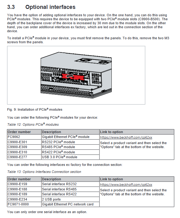
Optional extension interfaces and modules
It is divided into two categories: rear pre installed interfaces and PCIe expansion modules, all of which are designed for electrical isolation, and some are equipped with dedicated adapter cables.
PCIe expansion module (requires PCIe slot)
FC9062: Dual Gigabit Ethernet port module, supporting 100/1000Mbps;
C9900-E301: Dual RS232 serial port module, equipped with ix Industrial interface and 9-pin adapter cable;
C9900-E309: Dual RS485 module, factory half duplex, terminal resistance enabled;
C9900-E310: Dual RS42 module, factory full duplex, terminal resistance enabled;
C9900-E277: Dual USB 3.0 module, single port maximum 1A output.
Rear pre installed extension interface (directly exported from the factory)
C9900-E159: Single channel RS232;
C9900-E188: Single channel RS485;
C9900-E189: Single channel RS422;
C9900-E234: Dual USB 2.0;
FC9071: Single Gigabit Ethernet card.
All serial port modules have overvoltage protection, RS485/RS422 default working mode, and terminal resistance configuration are clearly marked in the document.
Nameplate, button and software adaptation
Equipment nameplate
The nameplate indicates complete equipment information: model (suffix distinguishes hardware version), serial number, production date, motherboard CPU、 Memory, storage, MAC addresses of various interfaces, batteries, and certification marks (CE, FCC, etc.) are the core basis for device traceability and spare parts matching.
Button Function
Standard computer button layout as standard, including directional keys, Home/End, PgUp/PgDn, Tab, Del, Enter, Shift, Ctrl, Alt, etc; The function keys and special indicator light keys can be customized and controlled by TwinCAT software.
TwinCAT version requirements
Different hardware versions correspond to the minimum TwinCAT version, which must meet the requirements in order to achieve full performance:
CP62xx-0070:TwinCAT 3.1 build 4022.0 / 2.11 b2259(x86);
CP62xx-0080/0090:TwinCAT 3.1 build 4026.16;
The manufacturer recommends always using the latest version.
Equipment installation and power on debugging
Transportation and unboxing
The internal components of the equipment have weak impact resistance, and the original packaging needs to be used for transportation; After transportation in a large temperature difference and low-temperature environment, it must be allowed to stand at room temperature. If condensation occurs, it must wait for more than 12 hours before being powered on.
Installation of control cabinet
Requirements for the thickness of cabinet openings: 1~5mm for conventional models and 1~3mm for stainless steel front panel models;
Heat dissipation requirements: 5cm ventilation space must be reserved above and below the device to avoid direct sunlight and screen reflection;
Installation method: Fixed with a back pressure bar, equipped with a 3.0mm hexagonal tool, strictly installed in the specified posture, and inverted or side mounted is prohibited.
Wiring specifications
Wiring sequence: First connect the ground wire, data wire, and finally connect the power wire; Do not plug or unplug cables during thunderstorms;
Grounding requirements: Simultaneously perform protective grounding and functional grounding, with a recommended grounding wire of ≥ 10mm ², following the EN 60204-1 standard. External equipment must ensure consistent potential;
UPS and Battery: Can be connected to the C9900-U330 dedicated battery pack, only original accessories can be used, the battery pack can achieve power-off endurance and second screen power supply.
Power on/off logic
PC-ON pin: 0V power on, 24V power off; The shutdown state should be maintained at 24V continuously until complete power is cut off, otherwise the device will restart;
Power Status output: After the whole machine is powered off, it outputs 0V, with a maximum load of 0.5A, and can be linked to external contactors;
Operation taboos: It is strictly prohibited to cut off the main power when the system is not shut down properly to prevent data loss and hard disk damage;
Touch screen usage: can only be operated with bare hands or dust-free gloves, can be equipped with original protective film, or set to cleaning mode through matching tools.
System configuration
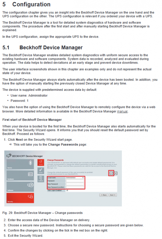
Beckhoff Device Manager
The device automatically starts when it is turned on, and can also be manually accessed by entering localhost/config through a browser for hardware diagnosis, status monitoring, and remote configuration. Factory default account: Administrator, password: 1. Password must be changed for the first login; It is recommended to set a high-strength password with a length of ≥ 10 characters, including uppercase and lowercase letters, numbers, and symbols. BIOS also recommends adding a password.
UPS configuration
When the device is equipped with UPS function, it is necessary to select the corresponding manufacturer, model, and communication port in the system to complete the configuration, and the supporting software and drivers should be pre installed at the factory. If there are no system devices, manual deployment is required.
Shutdown, disassembly, and disposal
Shutdown process: Shut down the system normally → Disconnect the 24V main power supply → Remove the data cable and grounding wire in sequence;
Disassembly: Release the pressure rod and remove the equipment from the cabinet opening;
Scrap and dismantling: Classify and recycle plastics, metals, and circuit boards according to local electronic waste regulations; The CR203 battery on the motherboard needs to be insulated with electrodes and then handed over to a professional battery recycling organization for disposal.
Daily maintenance and component replacement
Cleaning standards
The front panel (IP65) can use glass cleaner, alcohol isothermal and reagent; Prohibit the use of high-pressure water guns, compressed air, grinding and cleaning agents, and steam cleaning; It is recommended to activate the software cleaning mode before cleaning the touch screen.
Preventive replacement cycle (recommended)
Recommended replacement cycle for components
UPS battery pack for 5 years
2.5-inch/3.5-inch mechanical hard drive for 5 years (shortened operating time under high temperature conditions)
Cooling fan for 7 years
SSD/CFast flash memory for 10 years
Motherboard CR2032 battery for 5 years
Component replacement operation
Motherboard battery: Model CR2032 (3V lithium manganese battery), charging, disassembly, and incineration are prohibited, and the positive and negative poles should be distinguished when replacing;
Storage media (hard disk/SSD/CFast): Power off operation, system image backup and migration can be completed using Beckhoff BST tool; The storage layout may vary slightly among different models;
Cooling fan: To replace the back cover, original factory accessories must be used.
ESD anti-static requirements
Anti static measures (anti-static wristbands, anti-static tabletops, grounding) must be taken when disassembling and assembling electronic components to prevent static electricity from penetrating the circuit board.
Troubleshooting
Document summary of common faults, causes, and corresponding solutions:
The device is completely unresponsive: Check the power supply line and contact Beifu after-sales if there are still abnormalities;
Unable to complete boot up: restore BIOS default settings, report repair if invalid;
System startup but controller malfunction: investigate the upper software or external lower devices;
TwinCAT USB communication error: Adjust the communication cycle from the default 10ms to 50-80ms;
Screen black/local abnormality: Check for backlight or hardware faults and contact after-sales service for maintenance.
Overall technical parameters
Electrical parameters: power supply of 22-30 VDC (nominal 24 VDC), maximum current of 5.5 A; built-in fTPM 2.0 safety chip;
Protection level: front panel IP65, back interface area IP20;
Environmental parameters: working temperature of 0-55 ℃, storage and transportation temperature of -20~65 ℃, relative humidity ≤ 95% (no condensation);
Mechanical performance: compliant with EN 60068 vibration and impact standards, resistant to industrial vibration and short-term impact;
Electromagnetic compatibility: meets EN 61000-6-4 (radiated emission) and EN 61000-6-2 (anti-interference) requirements;
Certification: Standard international certifications such as CE, EAC, UKCA, FCC, etc.