Beckhoff EL41xx Series 16 Bit Analog Output Terminal Manual
Preface and Basic Standards
1. Product Overview
EL41xx is a 16 bit single ended analog output EtherCAT terminal, with a full range of electrical isolation and short-circuit protection. It is divided into two categories: 2-channel (EL41x2) and 4-channel (EL41x4). The output signal is divided into two categories: voltage and current
Voltage type
EL4102/04:0~+10V
EL4132/34:-10~+10V
current mode
EL4112/14:0~20mA; EL4112-0010:-10~+10mA
EL4122/24:4~20mA (industrial standard transmitter signal)
Calibration derivative models (suffix differentiation)
-0020: Original factory calibration certificate
-0030: DAkkS/ISO17025 third-party authoritative calibration certificate
2. Target audience and disclaimer for the document
Only for certified engineers familiar with national standards and automation control; Beifu reserves the right to modify documents and products without prior notice, and the content of the manual cannot be used as a basis for claims for changes to shipped products; Simultaneously label the entire series of trademarks, EtherCAT patent information, and copyright constraints.
3. Safety regulatory system
Hazard classification signs: DANGER (high risk of death), Warning (moderate to serious injury), CAUTION (mild injury), NOTICE (equipment/data damage)
Equipment identification system
14 bit device coding rules: series+model+version+revision (e.g. EL4102-0000-1016), with high revision versions being backward compatible;
8-digit serial number: production week+year+firmware version+hardware version;
BIC Beifu Identification Code (Data Matrix QR Code): including order number, unique BTN traceability code, material description, batch, etc; After 2020, the equipment supports eBIC electronic reading, TwinCAT can be viewed online, and the PLC library provides dedicated function block reading and parsing.
Version iteration record: V4.9 updates the basic function chapter, and historical versions continue to improve technical parameters, wiring diagnosis, and CoE parameter content.
Detailed specifications of each model of product
General Hardware Parameters (System 1)
Resolution: 16 bit signed synchronous sampling; Single ended grounding and output short-circuit protection; Electrical isolation 500V (E-Bus and on-site side);
Process image: 16 bit data per channel, no need to set dialing address;
Environment: Standard temperature range of 0-55 ℃, extended temperature range of -25~+60 ℃; Storage -40~+85 ℃; Humidity of 95% without condensation; Protection IP20; DIN35 rail installation;
Certification: CE, UKCA, EAC, cULus, supporting ATEX/IECEx explosion-proof certification (II 3 G Ex nA IIC T4 Gc);
Communication: Supports distributed clock DC, with sampling rates divided into two modes: DC on/off, with a maximum of 20kSps for 2 channels and 4kSps for 4 channels;
Core differences by model
1. 2-channel series (EL4102/112/112-0010/4122/4132)
EL4102 (0~10V): Load>5k Ω, E-Bus typical power consumption 170mA;
EL4112 (0~20mA)/EL4112-0010 (± 10mA): Load < 500 Ω, external 24V power supply for output;
EL4122 (4~20mA): Standard industrial circuit, load < 500 Ω;
EL4132 (± 10V): Bipolar voltage output, extended temperature condition accuracy ± 0.2% FS.
2. 4-channel series (EL4104/114/114-0020/4124/4134/4134-0020/-0030)
The four channel has a larger volume, with a typical E-Bus power consumption of 190mA; the current version has a load upper limit of 350 Ω; EL4134 is divided into basic models, in-house calibration models, and ISO third-party calibration models, suitable for high-precision measurement scenarios.
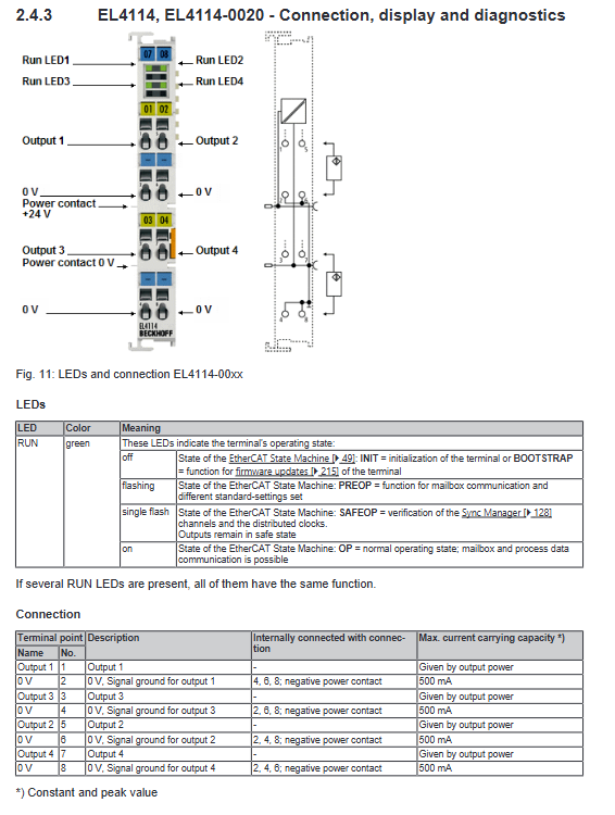
Terminal LED and Wiring Definition
The RUN green indicator light has four states: off (Initiat/firmware upgrade BOOT), flashing (PREOP email communication), single flashing (SAFEOP safety output lock), and constantly on (OP running normally);
Wiring: Spring terminals, distinguishing output lines, signal GND, 24V power contacts, and shielded terminals; Shielded wires are prohibited from carrying strong currents, and empty terminals are strictly prohibited from being wired; The current terminal comes with a 24V circuit power supply contact, and the voltage type is only powered by E-Bus.
EtherCAT Communication Fundamentals
1. Physical bus specifications
EtherCAT cable: Cat5 and above RJ45, with a maximum length of 100m between devices, supporting straight/crossover cables;
E-Bus Backplane Bus: The coupler has a maximum output of 2A, TwinCAT can calculate the total terminal current in real time, overload warning is highlighted in red, and EL9410 feeding terminals need to be installed for segmented power supply; The same terminal block E-Bus must be grounded together.
2. Watchdog mechanism
The ESC controller is equipped with two types of watchdogs, SM (Sync Manager) and PDI, with a default of 100ms. The timeout is calculated by a combination of frequency division registers and timing registers; After communication interruption, the output can be configured to maintain the original value, jump to 0, and gradually ramp up to the preset value; Disabling the watchdog will result in uncontrolled output during malfunctions.
3. EtherCAT State Machine ESM
Complete 5 operating states:
Initiate: Initialization, no email/process data;
PREOP: Only read and write email CoE parameters, no periodic IO;
SAFEOP: Sending and receiving process data, but outputting mandatory safety values;
OP: All functions are normal, and the output follows the instructions of the main station;
BOOT: Only for FoE firmware upgrade, business communication is prohibited.
4. CoE interface (CAN over EtherCAT)
Used for non periodic parameter configuration of terminals, using index+sub index hierarchical object dictionary:
0x1000 segment: read-only information for device identity, firmware, and serial number;
0x8000 segment: Channel output scaling, calibration, watchdog and other functional parameters;
0x6000/0x7000: Input/output PDO process data;
Parameter modification is stored in the terminal EEPROM by default, which can enable NoCoeStorage to prohibit writing and avoid flash memory loss; Support TwinCAT online reading and writing, PLC function block program reading and writing, configurable Startup startup list to achieve automatic recovery parameters for device replacement.
5. Distributed clock DC
EtherCAT local clock has an accuracy of ns level, and the master station synchronizes all slave stations with a synchronization accuracy of less than 100ns. It supports high-speed synchronous analog output.
Installation, wiring and explosion-proof, certification
1. ESD anti-static requirements
Release static electricity before operation, and do not touch the terminal spring directly; The end of the terminal block must be equipped with EL9011/9012 end caps to ensure ESD and protection level.
2. Explosion proof usage specifications (ATEX/IECEx)
Control cabinets with an IP54 rating or higher must be installed; Special provisions for distinguishing standard temperature range (0-55 ℃) and extended temperature range (-25~60 ℃);
Terminal plugging, wiring, replacing fuses, and adjusting dialing must be powered off/in a non explosive environment; The temperature resistant matching terminal of the cable heats up;
The accompanying independent explosion-proof manual can be downloaded from the official website.
3. Calibration certificate description
Ordinary EL41xx: Factory basic calibration, no paper certificate;
-0020: Beifu Factory Calibration Certificate;
-0030: DAkkS/ISO17025 third-party accreditation certificate;
The certificate binding device has a unique BTN serial number, which is only valid for a single device and records the factory environment and standard instruments.
4. Mechanical installation
DIN35 standard guide rail, orange buckle for disassembly and assembly operation; The internal spring of the terminal automatically connects the E-Bus and 24V power bus;
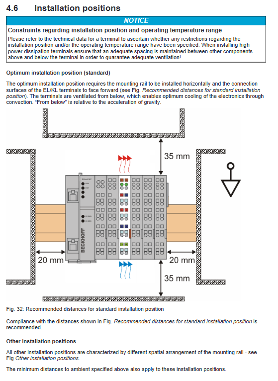
There are no mandatory restrictions on installation orientation, but horizontal installation is optimal for heat dissipation, with 20mm of ventilation reserved above and below;
Passive terminals cannot be continuously connected in series with more than 2 terminals; In high mechanical impact scenarios, it is necessary to fix the two ends of the guide rail and limit the total length of the terminal block.
5. Wiring specifications
Spring terminals are compatible with cables ranging from 0.08 to 2.5mm ², with an upper limit of 1.5mm ² for cables with wire noses; Forced use of twisted pair shielded wires for analog signals, shielded single point grounding; Disconnect the PE protective ground contact during insulation testing to avoid device breakdown.
6. Waste disposal
The equipment belongs to WEEE electrical waste, and it is prohibited to dispose of household waste. Local electronic waste regulations must be followed.
TwinCAT Debugging and Configuration
1. Complete debugging process for TwinCAT2/TwinCAT3
Preliminary preparation: Install EtherCAT real-time network card driver, import corresponding EL41xx series ESI device description XML file, and the software can automatically update the ESI library;
Two configuration modes:
Offline configuration: Hardware not powered on, manually adding terminals to build the project;
Online scanning: When the device is powered on, it automatically scans the EtherCAT topology to identify all EL terminals, supports configuration comparison, and differential color labeling (green matching/blue version difference/red missing);
PLC development: Supports IEC61131-3 full language (ST, LD, FBD, etc.), IO variables can automatically generate PLC structure and directly access analog output values without manual mapping;
Engineering import and export: supports XTI single device files, SCI standardized configuration files, and cross project reuse of terminal parameters;
2. EL41xx dedicated function configuration (EL41x2 two channel, EL41x4 four channel)
The firmware version distinguishes between two sets of feature sets:
Old version ESI (0000): Basic features (16 bit output, user scaling, watchdog default values);
New version of ESI (starting from 1016): Extended functions (user calibration, DC synchronization, watchdog ramp output);
Output operation link (PDO value → final analog signal):
Display format selection (signed/unsigned/absolute value) → User scaling (gain offset) → User/manufacturer calibration two options → Watchdog logic → DAC output;
Key parameters of CoE:
0x80n0 series: channel scaling, calibration enable, watchdog type, ramp rate;
Support custom fault output values, slow voltage/current rise and fall after disconnection;
PDO process data: Each channel has a fixed 2-byte 16 bit output data, which can be started and stopped in the synchronization manager SM for the corresponding channel PDO;
3. Diagnostic function
Bus diagnosis: WcState communication counter, EtherCAT operating state machine, synchronization error bit;
Channel diagnosis: Each channel outputs status words;
PLC library function block: Read BIC/BTN traceability code, set EtherCAT slave status, read and write CoE parameters, monitor load and communication abnormalities in real time.
4. Common engineering precautions
E-Bus current overload pop-up alarm, feeding terminal must be added;
When replacing terminals, high revision hardware is compatible with low version configurations, and low versions cannot use the new features added by high versions;
Start the list to store CoE parameters, and automatically issue configurations for device replacement without the need for re debugging;