Beckhoff BK series K-bus to EtherCAT coupler
Positioning differentiation of three couplers
BK1120, BK1150: K-Bus → EtherCAT master coupler
Function: Connect traditional KL series K-bus terminals to EtherCAT network;
Interface: Dual RJ45 EtherCAT ports (X1IN in/X2OUT out), supporting linear topology cascading;
Size: BK1120 width 49mm, BK1150 compact 12mm narrow module;
Equipped with independent K-bus power supply, it can mount up to 64 KL terminals and can be expanded to 255 with the KL9020 expansion module.
BK1250:E-Bus ↔ K-Bus hybrid coupler
Function: String in the backend of the EK series EtherCAT coupler to achieve mixing of EL (E-bus) and KL (K-bus) terminals on the same bus segment;
Only single EtherCAT input, no output cascade port;
Suitable for mixed use scenarios of new and old IO, compatible with over 300 KL traditional terminals.
General Core Technical Parameters
Communication: 100BASE-TX EtherCAT, supporting CoE/AoE, optional distributed clock DC;
IO capacity: The maximum input/output of a single coupler is 1024 bytes each, with a maximum of 8192 digital IO points and 256 analog channels;
Power supply: 24VDC (-15%~+20%), maximum output of 1750mA on BK1120/1150 K bus, only 500mA on BK1250; power contacts can continuously carry 10A;
Environment: Working temperature -25 ℃~+60 ℃, storage temperature -40~+85 ℃, humidity 95%, no condensation, IP20 protection;
Certification: CE, UKCA, cULus, EAC, ATEX II 3G Ex nA IIC T4 Gc;
Mechanical: DIN35 rail installation, compliant with EN60068 vibration and impact standards.
Core advantages of system architecture
Backward compatibility with existing KL terminals to protect hardware investments in old projects;
EtherCAT supports full topology (line, tree, star), with a maximum length of 100m for a single segment Ethernet cable;
Hardware FMMU real-time processing, thousand point IO refresh only 30 μ s, supports multi axis synchronization;
Built in 128KB local information table, automatically scans all KL terminals in the backend upon power on, and generates process images automatically.
Basic Working Principles
EtherCAT Core Mechanism
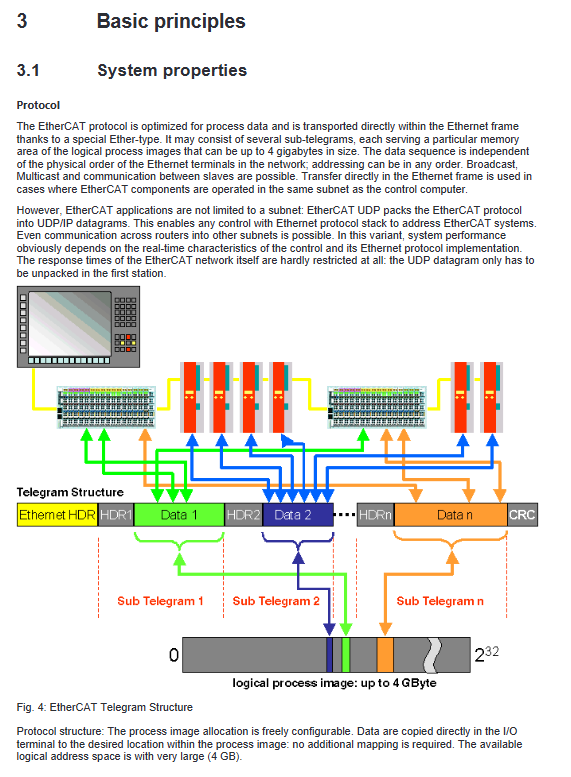
Message structure: Ethernet frames directly encapsulate process data, with a maximum logical image of 4GB, supporting broadcasting, cross UDP routing, and cross network segment communication;
Distributed clock DC: IEEE1588 synchronization, machine jitter<1 μ s, BK1150 new firmware supports as a DC reference clock;
Real time hardware: No CPU protocol stack overhead, supports cable redundancy, and segment by segment fault location.
Beckhoff Terminal Bus System
K-Bus: The internal data channel of the KL terminal backplane is interconnected by side spring plates, and the end must be equipped with KL9010 terminal resistors;
Potential isolation: multiple groups of 24V power supply circuits are divided through KL91xx feed terminal to realize electrical isolation of different sensors/actuators;
Fault safety: After bus disconnection/communication timeout, digital output is cut off, analog output defaults to 0V/0mA, and parameters are saved in the local register of the terminal in case of power failure.
CoE (CANopen over EtherCAT) protocol
Index+sub index hierarchical parameter system (0x0000~0xFFFF index);
0x1000: Device model and serial number read-only information;
0x8000: Channel configuration, filtering, calibration function parameters;
0x6000/0x7000: Input/output PDO process data;
Two access modes:
Offline: Read ESI file default parameters;
Online: Real time reading of the current hardware configuration of the coupler;
Startup Startup List: Automatically issue parameters after terminal replacement to avoid duplicate configuration; Support NoCoeStorage to disable EEPROM with repeated write protection lifetime.
EtherCAT State Machine ESM
Complete 5 standard slave states:
Init: Initialization, no email/process data;
Pre Op: Only CoE email communication, no periodic IO enabled;
Safe op: sends and receives periodic data, but outputs mandatory safety values;
Op: Normal operation, main station command output;
Boot: Dedicated for firmware upgrade, business communication is prohibited.
Installation and Wiring
ESD anti-static specifications
Release static electricity from the human body before operation, and do not touch the module’s shrapnel; The KL9010 end cap must be installed at the end of the entire terminal block to ensure ESD and IP20 protection.
DIN rail installation specifications
Horizontal installation is optimal, with a 20mm ventilation space reserved above and below; Insufficient vertical/side mounted heat dissipation prohibits long-term use;
The module splicing relies on the upper and lower buckles to engage, and the orange paddle unlocks and disassembles; Install fixed locking plates under high vibration conditions;
Mechanical reinforcement requirements: The fixed points of the guide rail are spaced 5cm apart, using countersunk screws, and the total length of the terminal group is limited.
Scrap disposal: Disassemble according to electronic waste regulations, classify and recycle metal shells and circuit boards.
Terminal Pin and Power Supply Definition
BK1120/BK1150, BK1250 share 8 spring terminals:
+24VUs/0VUs: The coupler itself is powered by the K bus;
+24VUp/0VUp: Peripheral power contact power supply, maximum 10A;
PE protection ground: Plug in priority conduction, can carry short-circuit high current, insulation testing requires disconnecting the PE.
Potential isolation architecture: The coupler power supply, K-bus, and field peripherals are electrically isolated from each other at 500V;
EtherCAT cabling: Minimum Cat5 Ethernet cable, RJ45 adaptive straight/crossover cable, recommended industrial shielded cable (ZB9010 series).
ATEX Explosion proof Service Conditions
It must be installed in a control cabinet with an IP54 rating or higher, and the dust scene must be upgraded to IP6X;
Environmental temperature limit -25~60 ℃;
All plugging, replacing fuses, and adjusting dialing operations must be powered off and removed from the explosion-proof area;
The temperature resistant matching terminal of the cable heats up, and the complete specifications can be found in the explosion-proof special manual.
UL Certification Instructions
The product has passed UL508 industrial control equipment certification and has only passed fire and electric shock safety testing.
Parameter Setting and Debugging
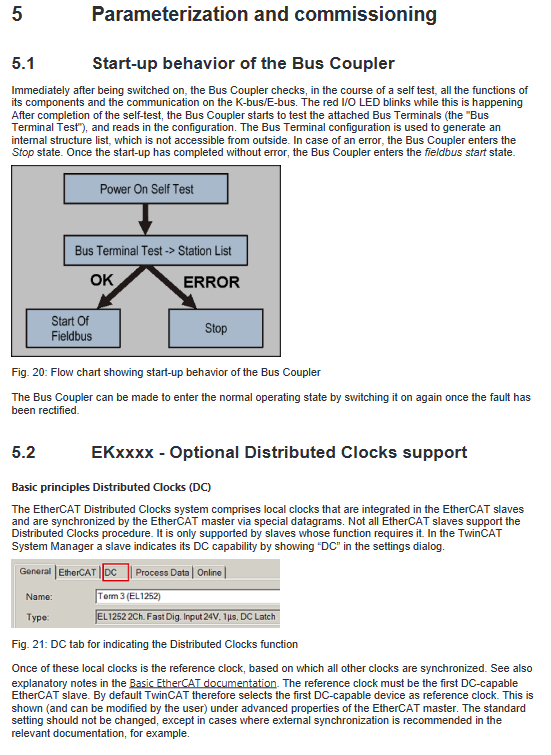
Power on self-test process
Two step automatic self check of coupling after power on:
Hardware self-test, I/O ERR red light flashing;
Scan all KL terminals in the backend to generate an internal device table;
If there is a self-test error, it will remain in a fault state, and the red light will continue to flash corresponding to the fault code.
Distributed Clock DC Configuration
The BK1150 high version firmware can be used as a DC reference clock, and in the TwinCAT EtherCAT advanced settings, select “Used as reference clock”; BK1120/BK1250 only supports synchronous slave stations.
Three parameter reading and writing methods for K-bus terminals
The coupler serves as a gateway to enable the EtherCAT master station to access the internal registers of the KL terminal
CoE Startup List (Recommended)
Pre op → Safe op stage automatically writes parameters, terminal replacement automatically restores; Operation process: Select terminal number → Enter unlock password 0x1235 → Modify register → Clear password and save. The complete example of KL3314 thermocouple is attached in the document.
Real time reading and writing of online CoE
The TwinCAT CoE Online page directly modifies registers, which is suitable for debugging, but does not save when powered off and needs to be added to the Startup list for solidification.
AoE(ADS over EtherCAT)
Generate coupler AmsNetID, PLC remotely reads and writes KL register through ADS function block, with TwinCAT3 example program attached.
TwinCAT System Manager Configuration Operation
BK1120/1150: Directly mount as an EtherCAT slave;
BK1250: mounted below the EK series EtherCAT coupler;
Core online monitoring variables:
CouplerState: K-bus, configuration fault flag;
CouplerCtrl: Control output enable;
WcState: Process data verification status;
State: EtherCAT current state machine;
AdSAddr: Communication address of coupler ADS.
PDO mapping rule: Analog terminals are mapped first, digital terminals are placed later, and the first 16 bits are fixed as coupler status/control words; The document includes a complete process image example.
KS2000 configuration software
Beifu Traditional KL Terminal Configuration Tool supports ADS communication connection to BK couplers, allowing for visual modification of terminal registers and export of configurations; Detailed step-by-step connection tutorial, suitable for on-site TwinCAT debugging scenarios without TwinCAT.
Troubleshooting and Diagnosis
Meaning of all LED indicator lights
BK1120/BK1150 indicator light
RUN green: EtherCAT status (constantly on OP, flashing Pre op, single flashing Safe op, off Init);
ERR red: Bus communication failure;
Us/UP green: The coupler and peripheral power supply are normal;
Link/ACT IN/OUT: Ethernet cable link/data flashing;
I/O ERR red: K-bus terminal fault, flashing pulse represents fault code.
BK1250 indicator light
Simplified panel, single EtherCAT chain street light, K-bus fault light, dual power supply indicator light.
I/O ERR Fault Code Comparison Table
Distinguish fault types through fast and slow pulses, including EEPROM verification errors, mismatched terminal numbers, K-bus open circuits, register communication failures, terminal model errors, etc; Fault location method: Split the terminal block in half and gradually troubleshoot the faulty KL module.
TwinCAT log error
A coupling fault will output a standard AL status code, with a typical error message:
0x0003: Safe op switching failed, K bus fault;
0x001e: Synchronization Manager SM configuration mismatch, inconsistent process image.