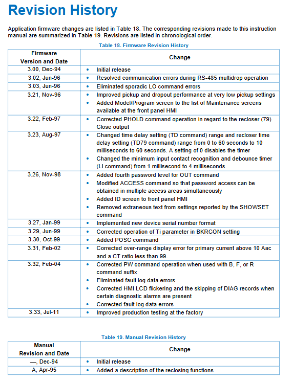
Basler BE1-BPR Circuit Breaker Protection Relay
Overview of core product functions
(1) Core Protection: Circuit Breaker Failure Protection (BFL)
The circuit breaker failure logic is the core of the whole machine, with 3 sets of standard version schemes (BFL1/BFL2/BFL3) and 3 sets of enhanced version schemes (BFL1E/BFL2E) built-in, suitable for three-phase three pole tripping, single pole tripping, and no current failure (no CT current due to internal transformer faults) scenarios:
Protection logic flow: The protection device sends a trip command (BFI input) → Delay timing (reserve circuit breaker opening time margin) → If the CT still detects fault current, it determines that the circuit breaker is malfunctioning and trips all adjacent backup circuit breakers;
Supporting auxiliary monitoring: Trip circuit continuity monitoring (TCM), real-time detection of trip coil breakage and fuse failure;
Adaptive logic: Adapt with pre inserted resistor circuit breakers to distinguish between high and low fault currents and set different failure delays.
(2) Automatic reclosing (79 function)
Independently running in parallel from failure protection, with a maximum of 3 reclosing cycles, each stroke delay is independently programmable, and comes with:
Reset timer (cooling reset after the fault disappears);
Overlap failure locking, maximum cycle time limit;
WAIT lock input (operation and maintenance, pause coincidence in case of failure), LOCKOUT permanently lock output;
The opening resistor is interlocked and locked to prevent overheating and damage to the resistor.
(3) Circuit breaker status diagnosis (enhanced exclusive)
Contact Loss Monitoring DLOG: Continuously accumulate I ² t of opening energy per phase, display contact wear as a percentage, automatically alert when exceeding limit, and support zero maintenance;
Opening resistor protection BKRRES: Count the number of resistor actions, output a locking coincidence signal after reaching the rated action limit, and reserve cooling time;
Fracture arc detector: Low level moving average current detector, which detects residual charging arc at the fracture after the circuit breaker is opened, automatically re opens or alarms to avoid burning out the arc extinguishing chamber.
(4) Fault recording and waveform recording
TLOG timing diagnosis log: records the margin of failure protection time (remaining delay after normal opening), with a maximum of 40 cycles stored. If the margin is too low, an automatic alarm will be triggered for optimization;
FLOG fault log (enhanced): stores fault time, phase current, input/output status;
COMTRADE waveform recording (enhanced): 4 weeks of pre recording for each fault+16 weeks of fault waveform, sampling 12 points/power frequency cycle, storing up to 12 sets of waveform recording, supporting Xmodem export of binary/ASCII standard files.
(5) Universal fault detection unit (3 independent fault detectors F1/F2/F3)
F1: Instantaneous phase overcurrent (1-cycle response, used for phase to phase short circuit failure criterion);
F2: Transient neutral grounding overcurrent;
F3: Moving average low current detector (dedicated for arc detection and weak charging current).
(6) Hardware input/output resources
7-way photoelectric isolation switch input (IN1~IN7): circuit breaker positions 5a/56a, BFI failure start, external lockout, waveform recording trigger; Input anti shake and recognition time software adjustable;
5 normally open hardware outputs OUT1~OUT5, 1 normally closed alarm output OA:
OUT1 high-speed malfunction tripping (1/4 cycle action);
OUT2 backup failure tripping, OUT3 coincidence locking, OUT4 arc alarm, OUT5 re tripping;
15 virtual internal outputs O6~O15, used for logical linkage and diagnostic alarms.
Human Machine Interface (HMI)
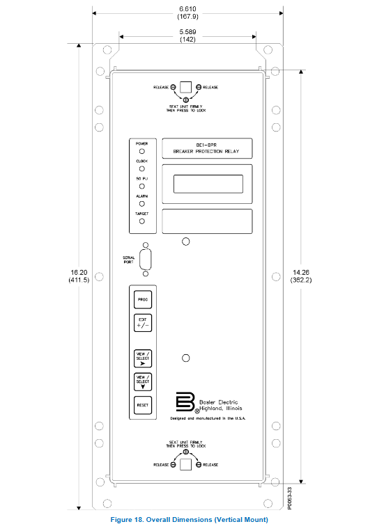
Front panel hardware: 2-line 16 character backlit LCD, 5 operation buttons (PROG programming, EDIT increase/decrease, up/down selection, RESET reset), multi status LED (power, clock not calibrated, overcurrent pickup, fault lock, alarm); Front RS232 local debugging port;
Main menu hierarchy (with slight differences between standard and enhanced menus):
Fault target → relay status → circuit breaker status → timing log → fault recording (only enhanced) → maintenance calibration;
Operation permissions: 4-level graded passwords (PW1~PW4), respectively controlling all parameters, protection settings, circuit breaker diagnosis, and output testing; Support only front panel/back panel/dual port permission restrictions;
Locking function: After the fault action, the LED is locked, and it will not be lost when the power is turned off. It needs to be manually reset or cleared with a communication command; Automatically return to the default display interface after 5 minutes of inactivity.
Principles of Hardware and Software Functionality
1. Hardware architecture
Isolation switch quantity acquisition, three-phase+neutral CT analog input, 12 bit ADC, DSP high-speed sampling, independent watchdog, isolation switch power supply; After a power outage, the large capacity capacitor maintains recorded data for about 24 hours; Automatic closing alarm contacts for machine malfunction and power loss.
Backplane communication: Front COM0 (RS232 local), Rear COM1A (RS232), COM1B (RS485 multi station bus); Support IRIG-B standard time synchronization, with millisecond time stamps used for SOE fault timing.
2. Software core: BEST logic programmable Boolean logic
The whole machine does not require hardware modification, and all inputs, timers, and output linkage can be customized through ASCII Boolean equations. Logical variables:
Input I1~I7, 6-way independent timers T1~T6, fault detectors F1/F2/F3, virtual outputs O1~O15;
Logical operators: AND (*), OR (+), NOT (/), support self-locking, interlocking, and delay window control.
Built in preset logic library: Standard version BFL1/BFL2/BFL3; Enhanced versions of BFL1E/BFL2E, as well as reclosing combination logic BF+79 and adaptive BFRES with opening resistors;
Support custom logic: copy preset scheme modifications, customize named storage to non-volatile storage, with a maximum erase life of one million times;
Timer differentiation: Delay timer (continuous timing to point output), Control window timer (valid output during timing period), all delay milliseconds/cycles/seconds adjustable.
Installation, wiring, and maintenance
Mechanical installation: horizontal 19 inch 3U rack, vertical embedded, provide hole drawings; Optional decorative cover panel; The whole machine can be installed at any angle;
Wiring specifications:
CT secondary wiring: Pull out the module to automatically short-circuit and prevent open circuits;
Switching input: Supports 48/125/250V DC, with onboard jumper switching between high and low voltage recognition;
Communication: RS485 twisted pair bus with 120 Ω terminal resistors at both ends; IRIG-B synchronous independent isolation terminal;
Power circuit wire ≥ 14AWG, grounding 12AWG independent copper wire;
Maintenance requirements:
No need for board level maintenance, replace the pull-out host directly if there is a malfunction and send it to the factory;
Idle spare parts can be powered on for 30 minutes every year to extend the lifespan of electrolytic capacitors;
The withstand voltage test requires disconnecting all communication and CT terminals, following the 1500Vac/1-minute withstand voltage standard.
Communication system
Port division:
COM0 (pre RS232): Local temporary debugging, highest priority;
COM1A (backplane RS232), COM1B (backplane RS485): long-term remote multi station monitoring; Only one port is working at the same time;
Communication protocol: Custom ASCII instruction set, supports single/multi line commands, separated by semicolons; Set unique IDs (1-254) for multi station mode and broadcast instructions to be executed across the entire network;
BESTview upper software: a Windows supporting tool that enables parameter reading and writing, waveform recording and export, logic editing, and fault analysis;
Core Communication Instruction Set:
Device recognition VER, parameter reading SHOWSET, logic LINFO/LN, timing TD, fault recording FL, timing TLOG, password PW, calibration CAL, clock TIME/DATE, etc; Support Xmodem transmission of COMTRADE recording files.
Calibration and whole machine testing process
Analog calibration: Apply standard 1A/5A CT secondary current, perform dual channel calibration for low range and high range, and pre-set the system frequency for 50/60Hz;
Step by step testing of the entire machine:
① Verification of power supply and communication ports; ② Switch input recognition and anti shake testing; ③ Fault detector startup/return current verification; ④ Complete timing test for failure protection; ⑤ The entire process of reclosing action; ⑥ Alarm and target indicator light latch verification; ⑦ Wave recording trigger test;
Output test: OUT command remote pulse drives all hardware contacts, verifies trip circuit;
After testing, all parameters and logic are stored in EEPROM using the SAVE instruction, and QUIT is exited without saving.
Key specifications of electrical machinery
Current acquisition: 1A/5A CT dual specifications, short-term withstand 50 times rated current;
Timing accuracy: Timer error ≤ 5ms, IRIG synchronization millisecond level;
Output contact capacity: AC 120V 7A long-term, DC 250V short-term 30A;
Environment: Working temperature -40 ℃~+70 ℃, resistant to vibration and impact, passed EMC surge and RF interference tests;
Storage: Wave recording, timing log, power-off cache for 24 hours;