Basler APR 63-5 Voltage Regulator
Product basic information
Product model: APR 63-5, material number 9168700107, Basler brushless generator excitation regulator
Applicable scenarios: Suitable for traditional brushless synchronous generators with a rated excitation magnetic field of 63Vdc, supporting 50/60Hz power frequency; Epoxy sealed sturdy plastic shell, certified by UL and CSA
Core principle: Collect the output voltage of the generator, convert the DC error signal, compare it with the reference voltage, adjust the excitation DC output in real time, and stabilize the terminal voltage of the unit
Complete electrical specification parameters
1. Power input (regulator working power supply)
Single phase AC: 190~277Vac (± 10%), 50/60Hz
Power consumption load: 650VA
2. Voltage acquisition input (PT sampling)
Single phase tap options: 240V/480V
240V:190~250Vac ±10%
480V:380~480Vac ±10%
Sampling power consumption up to 5VA; built-in voltage regulating potentiometer, external optional 1000 Ω/2W potentiometer for remote voltage regulation
240V internal voltage regulation range: 170~264Vac
480V internal voltage regulation range: 340~528Vac
3. Excitation power output (connected to the excitation machine magnetic field F+/F -)
Continuous rating: 5Adc, 63Vdc, 315W
1-minute strong excitation: 8.5Adc, 105Vdc, 893W
4. Environmental temperature
Operating temperature: -40 ℃~60 ℃
Storage temperature: -65 ℃~85 ℃
Three built-in adjustment knob functions
Panel configuration includes three adjustable potentiometers: FREQ, TAB, and VOLT
VOLT (Voltage)
Clockwise: Increase the output voltage of the generator; Reduce counterclockwise
Short circuit terminals 6 and 7 for local voltage regulation; Replace with a 1k Ω/2W potentiometer for remote ± 10% voltage regulation
Stab (Stability/Damping)
Control voltage response speed and suppress voltage oscillation:
Counter clockwise: response becomes faster, excessive response can cause continuous voltage oscillation (low-frequency oscillation)
Standard debugging: Rotate clockwise to the critical point where oscillation is eliminated
FREQ (frequency compensation/low frequency derating)
Automatically reduce output voltage at low speed/low frequency to protect the regulator and generator:
Debugging steps:
① The unit drops to the target low-frequency turning point speed; ② Rotate the FREQ knob until the voltage starts to decrease; ③ Restore the rated speed and return the voltage to the rated value
Characteristic curve: The turning point is at 55Hz for 60Hz units and 45Hz for 50Hz units, and the voltage drops linearly below this frequency
Overexcitation protection (core safety function)
1. Inverse time limit protection logic
Excitation voltage>100Vdc (± 5V): Delay cut-off of excitation, the delay duration is inversely proportional to the overvoltage amplitude, and the higher the voltage, the faster the trip
Excitation voltage ≥ 135Vdc (± 5V): Instantaneous cut-off of excitation output
2. Reset the locking logic
After the protective action cuts off the excitation, it will not automatically reset; The voltage regulator will only resume operation when the output voltage of the generator drops below 6Vac and lasts for more than 10 seconds.
Hardware installation and wiring specifications
1. Installation requirements
Can be installed at any angle and directly fix the unit; Two installation holes with a diameter of 0.218 inches; Fastener selection: # 11 American standard bolt or M5 metric
Terminal screw tightening torque ≤ 9 in lb (1N · m)
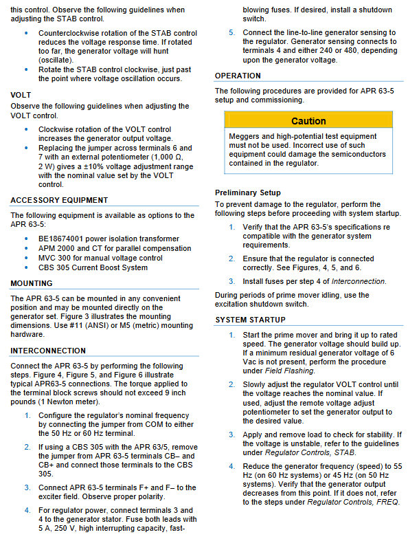
2. Standard wiring steps
Frequency jumper: Connect the COM terminal to a 50Hz or 60Hz terminal, matching the power frequency of the unit; Remove jumper wires when pairing with CBS305 parallel excitation components
Excitation circuit: Connect F+and F – to the excitation machine magnetic field, strictly distinguish between positive and negative poles
Voltage regulator power supply: terminals 3 and 4 are connected to the generator stator, and the circuit is equipped with a 5A high breaking speed fuse. A shutdown switch can be added
Voltage sampling: Terminal 4 and 240/480 taps are connected to the generator line voltage, and the tap is selected according to the rated voltage of the unit
Optional CBS305 Current Boosting Module: Remove CB+and CB – short circuits, connect external module
3. Optional accessories
BE18674001 power isolation transformer
APM2000 parallel compensation current transformer
MVC300 Manual Voltage Regulating Unit
CBS305 Current Enhancement System
4. Prohibited operations
It is strictly prohibited to use a megohmmeter or voltage tester to measure the regulator, as internal semiconductors are prone to high-voltage breakdown.
Operation process
1. Pre inspection (before startup)
Verify that the equipment parameters match the excitation specifications of the generator
Recheck all wiring polarity and terminal fastening
Confirm that the power supply circuit insurance has been installed in place
It is recommended to activate the excitation shutdown switch in low-speed idle scenarios
2. Unit start-up and commissioning
Start the prime mover to the rated speed and rely on residual magnetism for excitation (a minimum residual voltage of 6Vac can automatically build up the voltage); Perform magnetization process without residual voltage
Slowly adjust the VOLT knob to the rated output; Equipped with remote potentiometer synchronous calibration
Switch the load, observe voltage stability, and adjust the STAB damping knob for oscillation
Low frequency protection for speed reduction test: When the 60Hz unit drops to 55Hz/50Hz and drops to 45Hz, the voltage should automatically decrease. If there is an abnormality, adjust the FREQ knob again
3. Insufficient residual voltage and field flashing
When there is no voltage during the initial excitation of the unit:
Original engine shutdown; Connect a current limiting resistor (1 Ω per volt, power ≥ 1W/V) in series with a DC power supply of ≤ 48V to F+/F-
Disconnect the DC power supply after 30 seconds
Restart the unit and measure the sampling terminal voltage to be greater than 6Vac to establish normal voltage. Repeat the operation if it does not meet the standard
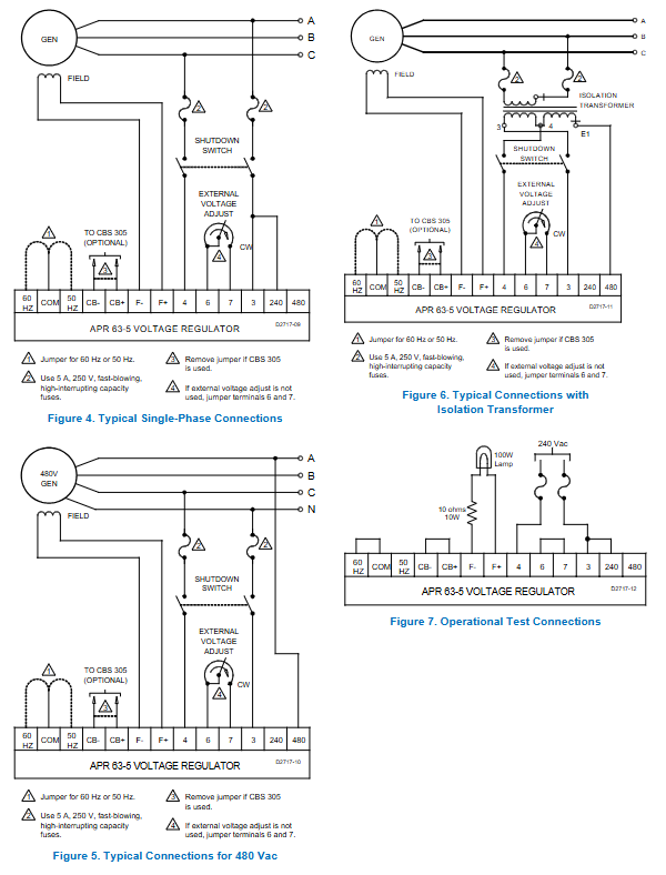
4. Test process for the entire machine on the test bench
Connect 240Vac sampling power supply
VOLT is completely counterclockwise, and the indicator light goes out; Completely clockwise, the indicator light is on
Pull back the knob until the light goes out, verify that the voltage regulation range is normal
Drawing and Curve Description
Figure 1 Frequency compensation curve: showing the voltage drop characteristics after the low-frequency inflection point of a 50/60Hz unit
Figure 2 Overexcitation inverse time curve: horizontal axis excitation DC voltage, vertical axis trip delay, 135Vdc delay approaching 0 (instantaneous protection)
Figure 3: Equipment appearance, installation dimensions, panel FREQ/TAB/VOLT knobs, all terminal identification
Figure 4-6: Three standard external wiring diagrams for single-phase 240V, 480V, and with isolation transformer
Figure 7: Schematic diagram of wiring for laboratory bench testing