Basler XR2002/XR2002F PMG excitation regulator
General Information and Electrical/Physical Specifications
(1) Core electrical performance parameters
Excitation DC output capability
Long term continuous: 7A/63V (440W);
Forced excitation for 1 minute short-term: 10A/90V (900W);
Suitable excitation winding DC resistance range: 9 Ω~100 Ω; If the winding is less than 9 Ω, a power limiting resistor must be connected in series. If the full load exceeds 7A, a high-power voltage regulator needs to be replaced.
There are two scenarios for communication input (power supply)
Scenario 1: PMG power supply
Single phase: No load 180Vac/Full load 100Vac, rated 120Vac;
Three phase: no load 140Vac/full load 70Vac, rated 80Vac;
Frequency range 48~480Hz;
Scenario 2: The generator’s outgoing line is powered by an isolated transformer
Single phase: No load 153Vac/Full load 90Vac; Three phase no-load 110Vac/full load 70Vac;
Terminal voltage sampling circuit
Supports 4-speed rated sampling: 120V/208/240V/416/480V/600Vac, with adjustment intervals of rated ± 10%; Sampling load: PMG power supply<5VA, external transformer<12VA; phase to phase sampling is required, phase to neutral is prohibited, and third harmonic interference is reduced.
Control accuracy and dynamic indicators
Voltage regulation accuracy: from no load to full load < ± 0.5%;
Temperature drift: 50 ℃ temperature difference voltage fluctuation<2%;
Response speed: less than 10ms under sampling voltage ± 10% disturbance;
Built in EMI electromagnetic interference filter, with a maximum power consumption of 75W for the entire machine.
(2) XR2002F exclusive frequency compensation function (two core differences)
Standard V/Hz voltage frequency characteristics: voltage and frequency decrease linearly, delaying voltage recovery when sudden load is applied, and improving load capacity; The UF ADJ knob on the panel adjusts the inflection point to 45-65Hz, with a factory preset of 55Hz.
Limiting VLV/Hz characteristics: precise voltage stabilization even under low frequency voltage reduction and small speed fluctuations, distinguishing between 50Hz/60Hz two sets of curves, adjusting the inflection point frequency through UF ADJ, balancing heavy load and steady-state voltage regulation.
Panel configuration: VOLT voltage adjustment, UF ADJ frequency compensation adjustment, and STAB stability adjustment with three adjustable knobs.
(3) Physical environment specifications
Working temperature: -40 ℃~+60 ℃; Storage -65 ℃~+85 ℃;
Anti vibration and impact: multi frequency vibration tolerance, three-axis 15G impact;
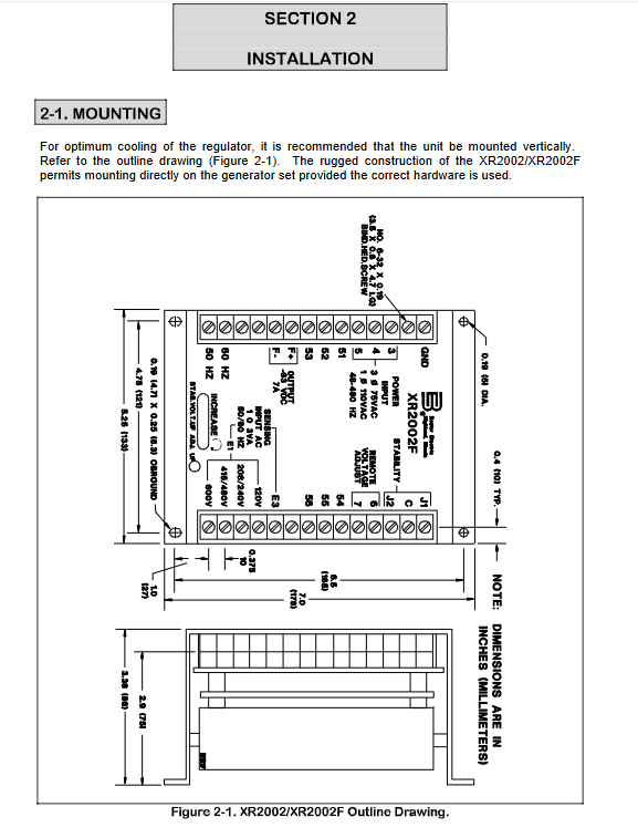
Weight: Net weight 1.1kg, packaging 1.4kg; it is recommended to arrange it vertically to ensure heat dissipation during installation.
Installation specifications, wiring, and accessories
1. Mechanical installation
Vertical installation of the whole machine is optimal, which can directly fix the unit base and comes with external dimension drawings; Standard specifications for shell openings.
2. Key points of excitation main circuit wiring
Connect the output terminals F+and F – to the excitation winding of the brushless excitation machine, and strictly distinguish the polarity; The winding resistance is less than 9 Ω, and a series power limiting resistor is used.
Prohibit excitation circuit series division demagnetization switch; If excitation needs to be cut off, remove the original short circuiting piece between F+and terminal 53, and connect the Basler 05407 single pole rotary switch externally.
All communication input phase lines must be equipped with high breaking capacity fuses.
3. Two complete wiring schemes
Option A: PMG as the power supply (Figure 2-2)
Single phase input terminals 3 and 4; Three phase input 3/4/5; Excitation output F+, F -; Machine end sampling E1/E3 is divided into four voltage levels, and the voltage terminals are matched with the generator.
Plan B: The generator output line is powered by an isolation transformer (Figure 2-3)
The main output is connected to the input of the voltage regulator through isolated PT; The secondary side of the transformer cannot be grounded (if the regulator casing is grounded);
Unique excitation circuit: When the residual voltage is insufficient or the polarity is incorrect, the external DC battery is excited, and the circuit is connected in series with diodes and current limiting resistors to provide an excitation current calculation formula; The excitation switch builds pressure within 15 seconds of closing at rated speed.
4. Voltage regulation configuration
Panel VOLT knob: clockwise boost; Short circuiting of terminals 6 and 7 at the factory;
External 500 Ω remote potentiometer R50: Remove the 6/7 short circuit, connect the potentiometer slider to 6, the voltage is the lowest when the resistance is the highest, and the panel knob changes to range adjustment.
5. Auxiliary terminals (51~56)
Used for expanding peripherals, the 54 terminal must be connected to an internal short circuit for normal operation; The old model 001~236 replaces the new version 55 with terminal 56, and wiring is prohibited without special peripherals.
System operation and debugging steps
1. Pre check before startup
Check the model, 50/60Hz frequency jumper (only XR2002F), remote potentiometer short connector, and 54 terminal short circuit;
Fuses, demagnetization switches, and stable jumpers shall be configured according to the table;
Initial position of knob 3: VOLT is the lowest counterclockwise position, STAB is in the middle, and UF remains at the factory settings.
The stable jumper is divided into two levels: J1-C for fast response and C-C for moderate response, which works in conjunction with the panel TAB knob to suppress voltage oscillations.
2. Complete startup process
Raise the rated speed of the prime mover and close the excitation switch;
Slowly rotate VOLT to the rated voltage; Paired with remote potentiometer for precise calibration;
Observe the voltage stability under no-load and loaded conditions respectively, and increase the STAB damping clockwise when oscillation occurs;
XR2002F was tested separately for its low-frequency V/Hz characteristics, and the voltage was verified to decrease with frequency during deceleration.
3. Sub item debugging steps
(1) Stability setting
Adjust the STAB to slight oscillation without load, and then eliminate it clockwise; Repeatedly switching the load with load to verify no oscillation, but still unstable. Replace the stable jumper gear.
(2) Debugging of V/Hz standard curve
Connect the corresponding 50/60Hz jumper; Rated voltage;
Turn UF ADJ clockwise until the indicator light is on, continue to lower the voltage to about 90% of the rated value, and then restore VOLT to the rated value to complete the low-frequency voltage reduction characteristic setting.
(3) Limiting VLV/Hz debugging
The speed drops to the target inflection point, adjust UF to make the indicator light just turn on, restore the rated speed, and the low-frequency voltage reduction function takes effect.
4. Suggestions for low-speed shutdown
It is recommended to cut off the excitation switch when the prime mover is idling to reduce regulator losses and extend its lifespan.
Troubleshooting and Factory Testing of the Whole Machine
(1) Six typical troubleshooting tables
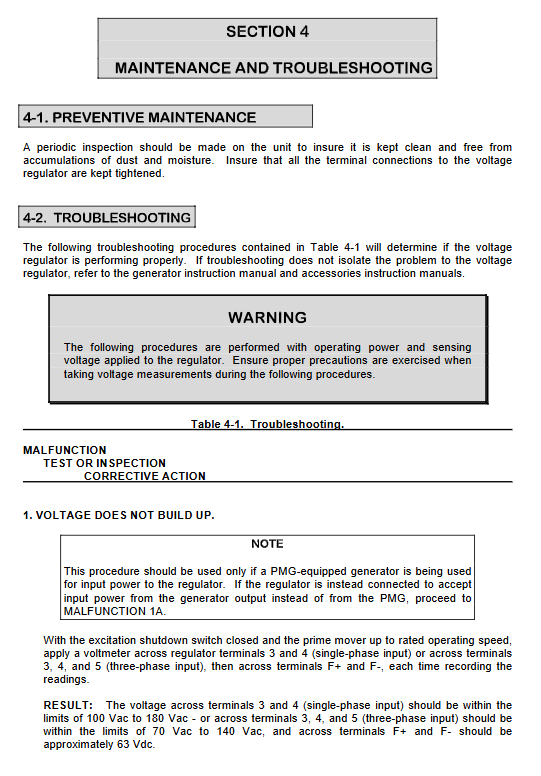
Unable to build pressure
There are two sets of measurement processes for PMG power supply and generator power supply: measuring input AC and excitation DC output; Check the fuse and circuit for abnormal input voltage; Input is normal but F+F – no 63V DC, indicating that the voltage regulator is damaged; The generator powered model can perform excitation operation.
Voltage repeatedly rises and falls, continuous oscillation: Short circuit the remote potentiometer terminal for testing, if ineffective, replace the regulator.
Voltage cannot be lowered due to high voltage: Disconnect the excitation switch, check if the sampling terminal matches the generator voltage, if there is no sampling voltage, check the PT and circuit, and replace the voltage regulator due to hardware failure.
Voltage regulation oscillation (hunting): First check the fluctuation of the prime mover speed, then adjust the TAB and stability jumper, and replace the equipment if it is ineffective.
Poor voltage regulation accuracy: Check the sampling points, use a rectifier voltmeter, and examine the impact of waveform distortion.
Sampling circuit fuse failure: There is a high probability of two grounding loops. Check for grounding.
(2) Offline factory testing of the entire machine
External 120V AC, 200W or less bulb simulated excitation load; Adjust the external potentiometer, the brightness of the light bulb changes smoothly with the potentiometer, and the response speed of the STAB counterclockwise switch is the normal judgment standard for the equipment. This test cannot reproduce on load oscillation faults.
Maintenance and replacement of spare parts
Daily maintenance: Regularly blow away dust and tighten all terminals;
Core replacement parts list: motherboard, various diodes, power transistors, 500 Ω 25W remote voltage regulator resistor R50, list the original Basler part number, and indicate the regulator model when reporting for repair.